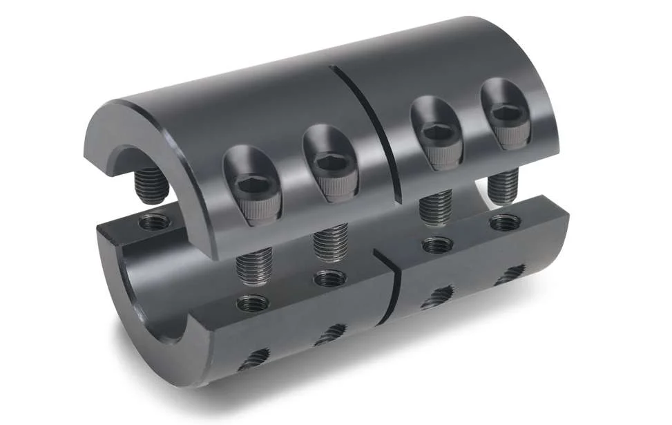
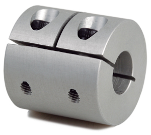
Product Description
Key attributes of CNC Long Rigid Pump Line Flexible Shaft Coupling for Model Shaft Connection
Industry-specific attributes of CNC Long Rigid Pump Line Flexible Shaft Coupling for Model Shaft Connection
| CNC Machining or Not | Cnc Machining |
| Material Capabilities | Aluminum, Brass, Bronze, Copper, Hardened Metals, Precious Metals, Stainless steel, Steel Alloys |
Other attributes of CNC Long Rigid Pump Line Flexible Shaft Coupling for Model Shaft Connection
| Place of Origin | ZheJiang , China |
| Type | Broaching, DRILLING, Etching / Chemical Machining, Laser Machining, Milling, Other Machining Services, Turning, Wire EDM |
| Model Number | OEM |
| Brand Name | OEM |
| Material | Metal |
| Process | Cnc Machining+deburrs |
| Surface treatment | Customer’s Request |
| Equipment | CNC Machining Centres / Core moving machine / precision lathe / Automatic loading and unloading equipment |
| Processing Type | Milling / Turning / Stamping |
| OEM/ODM | OEM & ODM CNC Milling Turning Machining Service |
| Drawing Format | 2D/(PDF/CAD)3D(IGES/STEP) |
| Our Service | OEM ODM Customers’drawing |
| Materials Avaliable | Stainless Steel / Aluminum / Metals / Copper / Plastic |
Best Seller of OEM/ODM Low MOQ Turning Milling Processing CNC Machined Component
About YiSheng
| Business Type | Factory / Manufacturer |
| Service | CNC Machining |
| Turning and Milling | |
| CNC Turning | |
| OEM Parts | |
| Material | 1). Aluminum: AL 6061-T6, 6063, 7075-T etc |
| 2). Stainless steel: 303,304,316L, 17-4(SUS630) etc | |
| 3). Steel: 4140, Q235, Q345B,20#,45# etc. | |
| 4). Titanium: TA1,TA2/GR2, TA4/GR5, TC4, TC18 etc | |
| 5). Brass: C36000 (HPb62), C37700 (HPb59), C26800 (H68), C22000(H90) etc | |
| 6). Copper, bronze, Magnesium alloy, Delrin, POM,Acrylic, PC, etc. | |
| Finish | Sandblasting, Anodize color, Blackenning, Zinc/Nickl Plating, Polish, |
| Power coating, Passivation PVD, Titanium Plating, Electrogalvanizing, | |
| electroplating chromium, electrophoresis, QPQ(Quench-Polish-Quench), | |
| Electro Polishing,Chrome Plating, Knurl, Laser etch Logo, etc. | |
| Main Equipment | CNC Machining center, CNC Lathe, precision lathe |
| Automatic loading and unloading equipment | |
| Core moving machine | |
| Drawing format | STEP,STP,GIS,CAD,PDF,DWG,DXF etc or samples. |
| Tolerance | +/-0.001mm ~ +/-0.05mm |
| Surface roughness | Ra 0.1~3.2 |
| Test Equipment | Complete test lab with Projector, High-low temperature test chamber, Tensile tester Gauge, Salt fog test |
| Inspection | Complete inspection lab with Micrometer, Optical Comparator, Caliper Vernier,CMM |
| Depth Caliper Vernier, Universal Protractor, Clock Gauge | |
| Capacity | CNC turning work range: φ0.5mm-φ150mm*300mm |
| CNC center work range: 510mm*850mm*500mm | |
| Core moving machine work range: φ32mm*85mm | |
| Gerenal Tolerance: (+/-mm) |
CNC Machining: 0.005 |
| Core moving: 0.005 | |
| Turning: 0.005 | |
| Grinding(Flatness/in2): 0.003 | |
| ID/OD Grinding: 0.002 | |
| Wire-Cutting: 0.002 |
RFQ of CNC Long Rigid Pump Line Flexible Shaft Coupling for Model Shaft Connection /* March 10, 2571 17:59:20 */!function(){function s(e,r){var a,o={};try{e&&e.split(“,”).forEach(function(e,t){e&&(a=e.match(/(.*?):(.*)$/))&&1

How to Properly Install a Rigid Shaft Coupling for Optimal Performance and Reliability
Proper installation of a rigid shaft coupling is essential to ensure optimal performance and reliability in mechanical systems. Here are the steps to follow for a successful installation:
- Shaft Preparation: Ensure that the shafts to be connected are clean, smooth, and free from any burrs or contaminants that could affect the coupling’s performance.
- Alignment: Align the two shafts accurately to minimize misalignment during installation. The alignment process is critical as any misalignment can lead to premature wear and reduced coupling efficiency.
- Fitment: Choose the appropriate size of the rigid shaft coupling that matches the shaft diameters. Carefully slide the coupling onto one shaft at a time.
- Fastening: For one-piece rigid couplings, ensure that the coupling is fitted snugly onto both shafts. For two-piece couplings, bolt the two halves together securely around the shafts.
- Tightening: Use the recommended torque value and follow the manufacturer’s guidelines to tighten the coupling bolts properly. Over-tightening can cause distortion, while under-tightening can lead to slippage and reduced torque transmission.
- Inspection: After installation, inspect the coupling to ensure that it is centered and aligned correctly. Check for any signs of misalignment or interference during rotation.
- Lubrication: Some rigid couplings may require lubrication at the friction points to reduce wear and friction. Follow the manufacturer’s recommendations for lubrication intervals and types.
- Load Testing: Perform load testing on the system to verify the coupling’s performance and check for any unusual vibrations or noises during operation.
- Regular Maintenance: Include the rigid coupling in your regular maintenance schedule. Periodically check for signs of wear, misalignment, or damage, and replace the coupling if necessary.
By following these installation steps and best practices, you can ensure that the rigid shaft coupling operates optimally, providing reliable torque transmission and contributing to the overall efficiency and longevity of the mechanical system.

Are there any safety considerations when using rigid shaft couplings in critical applications?
Yes, when using rigid shaft couplings in critical applications, several safety considerations should be taken into account:
- Torsional Stiffness: Rigid couplings have high torsional stiffness, which can lead to increased stresses and potential failures in the connected equipment. Proper analysis of torsional vibrations and stiffness compatibility with the connected components is crucial.
- Shaft Alignment: Inaccurate shaft alignment can lead to additional loads on the coupling and connected machinery. Precision alignment is essential to prevent premature wear, increased stress, and potential breakdowns.
- Overloading: Exceeding the rated torque capacity of the coupling can result in sudden failures and damage to machinery. It’s essential to operate within the coupling’s specified limits to ensure safe operation.
- Maintenance: Regular inspection and maintenance are critical to identify signs of wear, fatigue, or misalignment. Neglecting maintenance can lead to unexpected failures and safety hazards.
- Environmental Factors: Harsh environments, extreme temperatures, and corrosive substances can impact the integrity of rigid couplings. Choosing appropriate materials and protective measures can mitigate these effects.
For critical applications, it’s recommended to work closely with experienced engineers, perform thorough risk assessments, and follow industry standards and best practices to ensure the safe and reliable use of rigid shaft couplings.

Can Rigid Shaft Couplings Handle Misalignment Between Shafts Effectively?
Rigid shaft couplings are not designed to accommodate misalignment between shafts effectively. Unlike flexible couplings, which can bend or flex to some degree to compensate for misalignment, rigid couplings are inflexible and require precise alignment for proper operation.
When using rigid shaft couplings, it is crucial to ensure that the two shafts being connected are aligned with high accuracy. Misalignment between the shafts can lead to various issues, including:
- Vibrations: Misalignment can cause vibrations and increase stress on the coupling and connected machinery, leading to premature wear and reduced performance.
- Increased Stress: Misalignment results in additional stress on the shafts and coupling, which may lead to fatigue failure over time.
- Reduced Efficiency: Misalignment can result in power loss and reduced overall system efficiency.
- Noise: Misalignment may generate noise during operation, leading to potential discomfort for operators and additional wear on components.
To ensure the effective functioning of rigid shaft couplings, it is crucial to align the shafts accurately during installation. The alignment process typically involves using precision tools and techniques to achieve the desired alignment tolerances.
For applications where misalignment is expected or unavoidable, flexible couplings such as beam couplings or jaw couplings may be more suitable as they can accommodate slight misalignments and reduce the transmission of shock and vibration between shafts.
Overall, rigid shaft couplings are best suited for applications where precise shaft alignment is feasible and necessary for optimal performance. Proper alignment and regular maintenance are essential to maximize the life and efficiency of rigid couplings in mechanical systems.


editor by CX 2024-02-20