Product Description
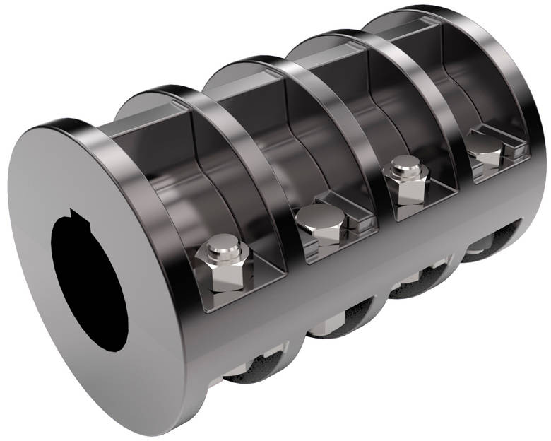
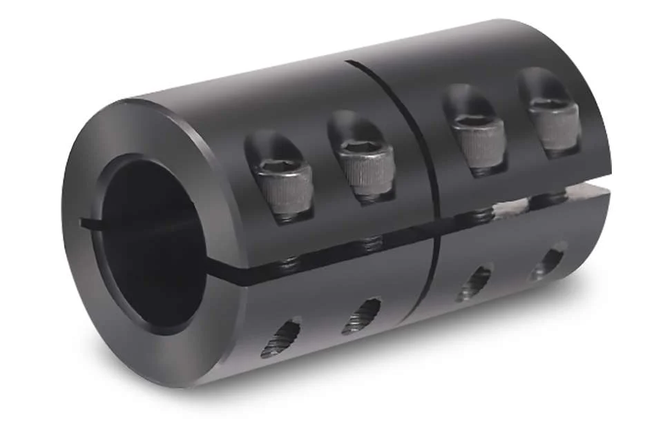
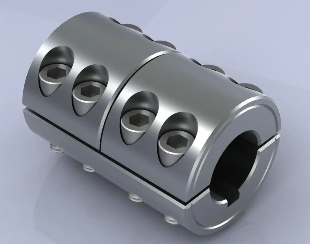
GNC-32×32 Rigid Shaft Coupling Rigid Clamping Coupling
GNC-32×32 Rigid Shaft Coupling Rigid Clamping Coupling
|
model parameter |
common bore diameter d1,d2 |
ΦD |
L |
F |
M |
tightening screw torque |
|
GNC-16×16 |
3,4,5,6,6.35,7,8 |
16 |
16 |
3.75 |
M2.5 |
1 |
|
GNC-16×24 |
3,4,5,6,6.35,7,8 |
16 |
24 |
3.75 |
M2.5 |
1 |
|
GNC-20×20 |
4,5,6,6.35,7,8,9,9.525,10 |
20 |
20 |
3.75 |
M2.5 |
1 |
|
GNC-20×30 |
4,5,6,6.35,7,8,9,9.525,10 |
20 |
30 |
3.75 |
M2.5 |
1 |
|
GNC-25×25 |
5,6,6.35,7,8,9,9.525,10,12 |
25 |
25 |
6 |
M3 |
1.5 |
|
GNC-25×36 |
5,6,6.35,7,8,9,9.525,10,12 |
25 |
36 |
6 |
M3 |
1.5 |
|
GNC-28.5×38 |
6,6.35,7,8,9,9.525,10,12,12.7,14 |
28.5 |
38 |
7.8 |
M4 |
2.5 |
|
GNC-32×32 |
6,6.35,7,8,9,9.525,10,12,12.7,14,15,16 |
32 |
32 |
7 |
M4 |
2.5 |
|
GNC-32×41 |
6,6.35,7,8,9,9.525,10,12,12.7,14,15,16 |
32 |
41 |
7.75 |
M4 |
2.5 |
|
GNC-40×44 |
8,9,9.525,10,11,12,12.7,14,15,15,17,18,19,20 |
40 |
44 |
10.5 |
M5 |
7 |
|
GNC-40×52 |
8,9,9.525,10,11,12,12.7,14,15,15,17,18,19,20 |
40 |
52 |
10.5 |
M5 |
7 |
|
GNC-50×55 |
10,11,12,12.7,14,15,16,17,18,19,20,22,24,25 |
50 |
55 |
13 |
M6 |
12 |
|
GNC-50×66 |
10,11,12,12.7,14,15,16,17,18,19,20,22,24,25 |
50 |
66 |
16 |
M6 |
12 |
|
GNC-63×71 |
10,11,12,12.7,14,15,16,17,18,19,20,22,24,25,28,30,32,35 |
63 |
71 |
16.5 |
M6 |
12 |
|
model parameter |
Rated torque(N.m) |
maximum speed (rpm) |
weight (g) |
|
GNC-16×16 |
5 |
1000 |
7 |
|
GNC-16×24 |
5 |
9400 |
13 |
|
GNC-20×20 |
10 |
7500 |
15 |
|
GNC-20×30 |
10 |
7500 |
25 |
|
GNC-25×25 |
12 |
6000 |
29 |
|
GNC-25×36 |
12 |
6000 |
43 |
|
GNC-28.5×38 |
14 |
5500 |
48 |
|
GNC-32×32 |
15 |
4700 |
55 |
|
GNC-32×41 |
15 |
4700 |
65 |
|
GNC-40×44 |
19 |
4000 |
123 |
|
GNC-40×52 |
19 |
4000 |
150 |
|
GNC-50×55 |
45 |
4000 |
240 |
|
GNC-50×66 |
45 |
4000 |
280 |
|
|
|
|
320 |
/* March 10, 2571 17:59:20 */!function(){function s(e,r){var a,o={};try{e&&e.split(“,”).forEach(function(e,t){e&&(a=e.match(/(.*?):(.*)$/))&&1

Can rigid shaft couplings operate in high-temperature or corrosive environments?
Rigid shaft couplings can be designed and manufactured using materials that are suitable for high-temperature or corrosive environments. Common materials used for such applications include stainless steel, nickel alloys, and other corrosion-resistant materials. These materials can withstand elevated temperatures and resist the effects of corrosive substances. When selecting a rigid shaft coupling for high-temperature or corrosive environments, it is essential to consider factors such as the operating temperature range, the specific corrosive substances present, and the overall environmental conditions. Additionally, proper lubrication and maintenance are crucial to ensuring the longevity and optimal performance of rigid couplings in these demanding environments. It is essential to consult with coupling manufacturers or suppliers who specialize in providing solutions for high-temperature or corrosive applications. They can help identify the appropriate materials and designs that will meet the specific requirements of the intended environment.

Can rigid shaft couplings be used for shafts with different rotational speeds and directions?
Rigid shaft couplings are typically designed for applications where the connected shafts have the same rotational speed and direction. They are not well-suited for scenarios involving significant speed differences or reverse rotation between shafts. The limitations arise from the coupling’s rigid construction, which does not allow for the compensation of speed differentials or changes in direction.
When shafts have different rotational speeds or need to rotate in opposite directions, it can result in uneven loading, increased wear, vibrations, and even coupling failure. Rigid couplings lack the flexibility required to accommodate the variations in speed and direction, which can lead to undesirable consequences in the system.
If your application involves shafts with varying speeds or reverse rotation, it’s recommended to explore flexible coupling options. Flexible couplings, such as gear couplings, elastomeric couplings, or universal joints, are designed to handle these situations by providing a degree of angular and radial flexibility. These couplings can help distribute the loads more evenly, reduce vibrations, and compensate for speed differences, ultimately contributing to smoother and more reliable operation.
It’s essential to accurately assess the requirements of your application and choose the appropriate coupling type based on the specific operational conditions. If there are varying speeds or reverse rotation involved, opting for flexible couplings designed for such scenarios will help ensure the longevity, efficiency, and performance of your machinery.

How Rigid Shaft Couplings Ensure Precise and Torque-Resistant Shaft Connections
Rigid shaft couplings are designed to provide a solid and inflexible connection between two shafts, ensuring precise alignment and efficient torque transmission. The key features that enable rigid couplings to achieve this include:
- One-Piece Construction: Rigid shaft couplings are typically made from a single piece of material, often metal, without any moving parts or flexible elements. This one-piece construction eliminates the risk of component failure and ensures a stable connection between the shafts.
- Accurate Machining: Rigid couplings undergo precise machining processes to achieve tight tolerances and accurate dimensions. This precision machining ensures that the coupling fits perfectly onto the shafts without any gaps or misalignments.
- High-Quality Materials: Rigid couplings are commonly manufactured from materials such as steel or aluminum, which offer excellent strength and durability. These high-quality materials contribute to the coupling’s ability to handle high torque loads without deformation or wear.
- Keyways and Set Screws: Many rigid shaft couplings feature keyways and set screws for additional security. Keyways are slots on the coupling and shafts that allow the transmission of torque without slippage. Set screws, when tightened against the shafts, create a firm grip, preventing axial movement and enhancing torque resistance.
- Clamping Force: Rigid couplings rely on a clamping force to hold the shafts firmly together. When the coupling is fastened around the shafts, the clamping force creates a strong bond between the coupling and shafts, minimizing any relative movement.
By combining these design elements, rigid shaft couplings ensure that the connected shafts remain in perfect alignment during operation. This precise alignment reduces the risk of misalignment-related issues such as vibrations, premature wear, and decreased efficiency. Additionally, the rigid nature of these couplings allows them to transmit torque without any backlash, providing immediate and accurate responsiveness to changes in torque and rotational direction.
Overall, rigid shaft couplings are an excellent choice for applications that demand precise shaft connections and reliable torque transmission. However, it’s essential to consider factors such as shaft alignment, load capacity, and environmental conditions when selecting the appropriate coupling for a specific application.
“`

editor by CX 2024-02-23