Product Description
Excellent powder metallurgy parts metallic sintered parts
We could offer various powder metallurgy parts including iron based and copper based with top quality and cheapest price, please only send the drawing or sample to us, we will according to customer’s requirement to make it. if you are interested in our product, please do not hesitate to contact us, we would like to offer the top quality and best service for you. thank you!
How do We Work with Our Clients
1. For a design expert or a big company with your own engineering team: we prefer to receive a fully RFQ pack from you including drawing, 3D model, quantity, pictures;
2. For a start-up company owner or green hand for engineering: just send an idea that you want to try, you don’t even need to know what casting is;
3. Our sales will reply you within 24 hours to confirm further details and give the estimated quote time;
4. Our engineering team will evaluate your inquiry and provide our offer within next 1~3 working days.
5. We can arrange a technical communication meeting with you and our engineers together anytime if required.
| Place of origin: | Jangsu,China |
| Type: | Powder metallurgy sintering |
| Spare parts type: | Powder metallurgy parts |
| Machinery Test report: | Provided |
| Material: | Iron,stainless,steel,copper |
| Key selling points: | Quality assurance |
| Mould type: | Tungsten steel |
| Material standard: | MPIF 35,DIN 3571,JIS Z 2550 |
| Application: | Small home appliances,Lockset,Electric tool, automobile, |
| Brand Name: | OEM SERVICE |
| Plating: | Customized |
| After-sales Service: | Online support |
| Processing: | Powder Metallurgr,CNC Machining |
| Powder Metallurgr: | High frequency quenching, oil immersion |
| Quality Control: | 100% inspection |
The Advantage of Powder Metallurgy Process
1. Cost effective
The final products can be compacted with powder metallurgy method ,and no need or can shorten the processing of machine .It can save material greatly and reduce the production cost .
2. Complex shapes
Powder metallurgy allows to obtain complex shapes directly from the compacting tooling ,without any machining operation ,like teeth ,splines ,profiles ,frontal geometries etc.
3. High precision
Achievable tolerances in the perpendicular direction of compacting are typically IT 8-9 as sintered,improvable up to IT 5-7 after sizing .Additional machining operations can improve the precision .
4. Self-lubrication
The interconnected porosity of the material can be filled with oils ,obtaining then a self-lubricating bearing :the oil provides constant lubrication between bearing and shaft ,and the system does not need any additional external lubricant .
5. Green technology
The manufacturing process of sintered components is certified as ecological ,because the material waste is very low ,the product is recyclable ,and the energy efficiency is good because the material is not molten.
FAQ
Q1: What is the type of payment?
A: Usually you should prepay 50% of the total amount. The balance should be pay off before shipment.
Q2: How to guarantee the high quality?
A: 100% inspection. We have Carl Zeiss high-precision testing equipment and testing department to make sure every product of size,appearance and pressure test are good.
Q3: How long will you give me the reply?
A: we will contact you in 12 hours as soon as we can.
Q4. How about your delivery time?
A: Generally, it will take 25 to 35 days after receiving your advance payment. The specific delivery time depends on the items and the quantity of your order. and if the item was non standard, we have to consider extra 10-15days for tooling/mould made.
Q5. Can you produce according to the samples or drawings?
A: Yes, we can produce by your samples or technical drawings. We can build the molds and fixtures.
Q6: How about tooling Charge?
A: Tooling charge only charge once when first order, all future orders would not charge again even tooling repair or under maintance.
Q7: What is your sample policy?
A: We can supply the sample if we have ready parts in stock, but the customers have to pay the sample cost and the courier cost.
Q8: How do you make our business long-term and good relationship?
A: 1. We keep good quality and competitive price to ensure our customers benefit ;
2. We respect every customer as our friend and we sincerely do business and make friends with them, no matter where they come from.
/* March 10, 2571 17:59:20 */!function(){function s(e,r){var a,o={};try{e&&e.split(“,”).forEach(function(e,t){e&&(a=e.match(/(.*?):(.*)$/))&&1

Can Rigid Shaft Couplings Accommodate Different Shaft Sizes and Handle High Torque Loads?
Yes, rigid shaft couplings are designed to accommodate different shaft sizes and are capable of handling high torque loads. One of the key advantages of rigid couplings is their ability to provide a solid and strong connection between two shafts.
Rigid shaft couplings come in various designs, such as one-piece and two-piece configurations. The one-piece couplings have a solid construction with no moving parts and are ideal for applications where precise alignment and torque transmission are essential.
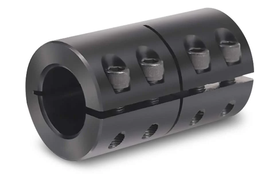
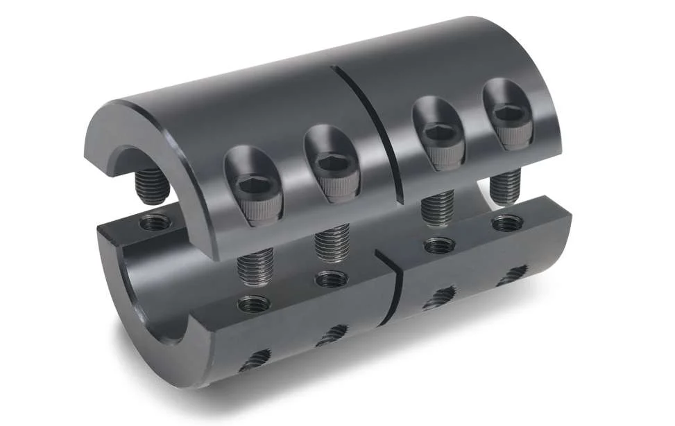
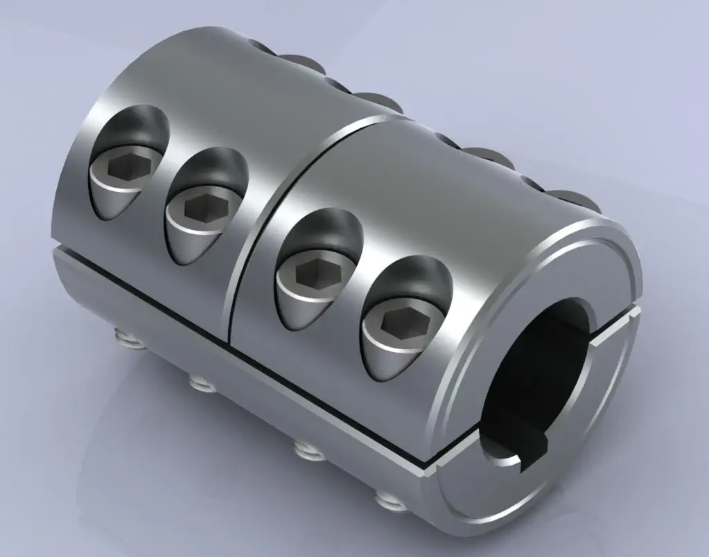
The two-piece rigid couplings consist of two halves that are bolted together around the shafts, creating a tight and secure connection. These couplings allow for easier installation and removal without the need to move the connected shafts. They are commonly used in applications where frequent maintenance is required.
The design of rigid shaft couplings enables them to handle high torque loads efficiently. The solid and rigid construction allows for the direct transfer of torque from one shaft to another, minimizing power loss and ensuring precise torque transmission.
Moreover, rigid couplings can accommodate different shaft sizes by offering various bore diameters and keyway options. This adaptability allows users to connect shafts of different diameters without the need for additional modifications or couplings.
However, it is crucial to select the appropriate size and type of rigid coupling based on the specific application’s torque requirements and shaft sizes. Properly sized rigid couplings will ensure reliable and efficient power transmission while preventing issues such as misalignment, vibration, and premature wear.

Are there any real-world case studies or success stories of using rigid shaft couplings in various engineering projects?
While specific case studies might not be readily available, there are numerous real-world examples of using rigid shaft couplings in various engineering projects across industries. These projects highlight the versatility and benefits of rigid shaft couplings in different applications:
- Industrial Machinery: Rigid shaft couplings are commonly used in industrial machinery such as conveyor systems, pumps, compressors, and machine tools. They ensure precise torque transmission, alignment, and stability in these critical applications, contributing to reliable and efficient operation.
- Robotics: Robotics often require accurate and repeatable motion control. Rigid couplings provide a rigid connection between robotic joints and actuators, ensuring precise movement and positioning.
- Aerospace: In aerospace applications, where safety and reliability are paramount, rigid shaft couplings play a role in connecting various components, such as engine components and control surfaces, ensuring consistent and reliable performance.
- Medical Equipment: Rigid couplings are used in medical devices such as diagnostic equipment, laboratory instruments, and surgical tools. They contribute to accurate motion control and sample manipulation.
- Automotive: Rigid shaft couplings can be found in automotive systems, including drivetrains and transmission systems. They ensure efficient torque transmission and alignment in components such as steering columns.
- Printing and Packaging: Printing presses and packaging machinery rely on rigid couplings to maintain precise alignment between rollers and components, ensuring consistent print quality and packaging accuracy.
While these examples illustrate the broad range of applications where rigid shaft couplings are used, it’s important to note that the success of each project is influenced by factors beyond just the coupling. Proper installation, maintenance, and integration into the overall system are crucial for achieving optimal results.
When considering the implementation of rigid shaft couplings in a project, engineers should collaborate with coupling manufacturers, suppliers, and experienced professionals to ensure proper selection, installation, and operation. By leveraging the advantages of rigid couplings, engineering projects can benefit from improved efficiency, reliability, and performance.

How Rigid Shaft Couplings Ensure Precise and Torque-Resistant Shaft Connections
Rigid shaft couplings are designed to provide a solid and inflexible connection between two shafts, ensuring precise alignment and efficient torque transmission. The key features that enable rigid couplings to achieve this include:
- One-Piece Construction: Rigid shaft couplings are typically made from a single piece of material, often metal, without any moving parts or flexible elements. This one-piece construction eliminates the risk of component failure and ensures a stable connection between the shafts.
- Accurate Machining: Rigid couplings undergo precise machining processes to achieve tight tolerances and accurate dimensions. This precision machining ensures that the coupling fits perfectly onto the shafts without any gaps or misalignments.
- High-Quality Materials: Rigid couplings are commonly manufactured from materials such as steel or aluminum, which offer excellent strength and durability. These high-quality materials contribute to the coupling’s ability to handle high torque loads without deformation or wear.
- Keyways and Set Screws: Many rigid shaft couplings feature keyways and set screws for additional security. Keyways are slots on the coupling and shafts that allow the transmission of torque without slippage. Set screws, when tightened against the shafts, create a firm grip, preventing axial movement and enhancing torque resistance.
- Clamping Force: Rigid couplings rely on a clamping force to hold the shafts firmly together. When the coupling is fastened around the shafts, the clamping force creates a strong bond between the coupling and shafts, minimizing any relative movement.
By combining these design elements, rigid shaft couplings ensure that the connected shafts remain in perfect alignment during operation. This precise alignment reduces the risk of misalignment-related issues such as vibrations, premature wear, and decreased efficiency. Additionally, the rigid nature of these couplings allows them to transmit torque without any backlash, providing immediate and accurate responsiveness to changes in torque and rotational direction.
Overall, rigid shaft couplings are an excellent choice for applications that demand precise shaft connections and reliable torque transmission. However, it’s essential to consider factors such as shaft alignment, load capacity, and environmental conditions when selecting the appropriate coupling for a specific application.
“`

editor by CX 2024-01-10