Product Description
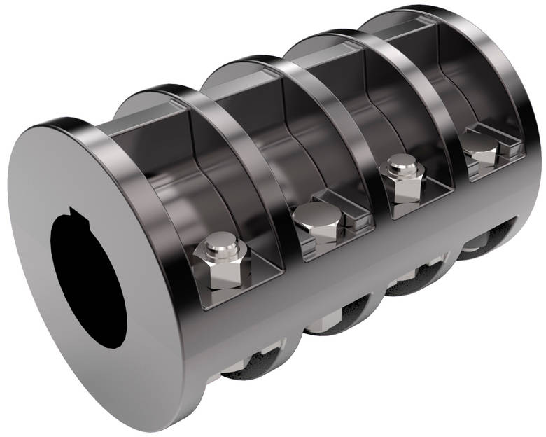
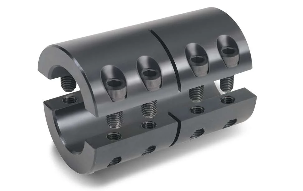
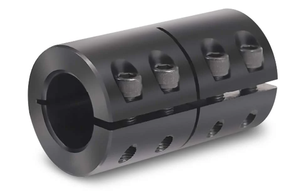
GR Motor Shaft Coupling Rigid Coupling
Description of GR Motor Shaft Coupling Rigid Coupling
>The material is aluminum alloy, and the middle bellows is made of stainless steel with excellent corrosion resistance
>Laser welding is used between bellows and shaft sleeve, with zero rotation clearance, suitable for CHINAMFG and reverse rotation
>Bellows structure can effectively compensate radial, angular and axial deviation
>Designed for servo motor stepper motor
>Fastening method of setscrew
Catalogue of GR Motor Shaft Coupling Rigid Coupling
|
model parameter |
common bore diameter d1,d2 |
ΦD |
L |
LI |
L2 |
L3 |
N |
F |
tightening screw torque |
|
GR-16×27 |
4,5,6,6.35,7,8 |
16 |
27 |
7.5 |
2 |
8 |
13.5 |
3 |
0.7 |
|
GR-20×32 |
5,6,6.35,7,8,9,9.525,10,11,12 |
20 |
32 |
7.2 |
2.8 |
12 |
18 |
3.5 |
0.7 |
|
GR-22.5×34 |
5,6,6.35,7,8,9,9.525,10,11,12 |
22.5 |
34 |
8.05 |
2.8 |
12.3 |
20.2 |
4.5 |
1.7 |
|
GR-25×37 |
6,6.35,7,8,9,9.525,10,11,12 |
25 |
37 |
9.5 |
3 |
12 |
20.2 |
4.5 |
1.7 |
|
GR-32×42 |
8,9,10,11,12,12.7,14,15 |
32 |
42 |
8 |
4 |
18 |
27.2 |
5.5 |
4 |
|
GR-40×51 |
8,9,9.525,10,11,12,12.7,14,15,16,17,18,19,20 |
40 |
51 |
9.5 |
6 |
20 |
34.5 |
5.5 |
4 |
|
GR-55×57 |
10,11,12,12.7,14,15,16,17,18,19,20,22,24,25 |
55 |
57 |
9 |
6 |
27 |
51.9 |
6.25 |
7 |
|
GR-65×81 |
10,11,12,12.7,14,15,16,17,18,19,20,22,24,25,28,30,32,35,38 |
65 |
81 |
19.5 |
7 |
28 |
60.5 |
8.9 |
7 |
|
model parameter |
Rated torque(N.m) |
allowable eccentricity (mm) |
allowable deflection angle (°) |
allowable axial deviation (mm) |
maximum speed (rpm) |
static torsional stiffness (N.M/rad) |
weight (g) |
|
GR-16×27 |
0.8 |
0.1 |
2 |
-0.8 |
20000 |
150 |
8 |
|
GR-20×32 |
1.5 |
0.1 |
2 |
-1.2 |
18000 |
220 |
13 |
|
GR-22.5×34 |
1.8 |
0.15 |
2 |
-1.2 |
16000 |
300 |
22 |
|
GR-25×37 |
2 |
0.15 |
2 |
-1.2 |
15000 |
330 |
30 |
|
GR-32×42 |
2.5 |
0.2 |
2 |
-1.7 |
11000 |
490 |
53 |
|
GR-40×51 |
6.4 |
0.3 |
2 |
-1.7 |
10000 |
530 |
85 |
|
GR-55×57 |
12 |
0.3 |
2 |
-1.7 |
9000 |
860 |
170 |
|
GR-65×81 |
18 |
0.2 |
2 |
-1.8 |
4500 |
900 |
280 |
/* January 22, 2571 19:08:37 */!function(){function s(e,r){var a,o={};try{e&&e.split(“,”).forEach(function(e,t){e&&(a=e.match(/(.*?):(.*)$/))&&1

Can rigid shaft couplings operate in high-temperature or corrosive environments?
Rigid shaft couplings can be designed and manufactured using materials that are suitable for high-temperature or corrosive environments. Common materials used for such applications include stainless steel, nickel alloys, and other corrosion-resistant materials. These materials can withstand elevated temperatures and resist the effects of corrosive substances. When selecting a rigid shaft coupling for high-temperature or corrosive environments, it is essential to consider factors such as the operating temperature range, the specific corrosive substances present, and the overall environmental conditions. Additionally, proper lubrication and maintenance are crucial to ensuring the longevity and optimal performance of rigid couplings in these demanding environments. It is essential to consult with coupling manufacturers or suppliers who specialize in providing solutions for high-temperature or corrosive applications. They can help identify the appropriate materials and designs that will meet the specific requirements of the intended environment.

Are there any safety considerations when using rigid shaft couplings in critical applications?
Yes, when using rigid shaft couplings in critical applications, several safety considerations should be taken into account:
- Torsional Stiffness: Rigid couplings have high torsional stiffness, which can lead to increased stresses and potential failures in the connected equipment. Proper analysis of torsional vibrations and stiffness compatibility with the connected components is crucial.
- Shaft Alignment: Inaccurate shaft alignment can lead to additional loads on the coupling and connected machinery. Precision alignment is essential to prevent premature wear, increased stress, and potential breakdowns.
- Overloading: Exceeding the rated torque capacity of the coupling can result in sudden failures and damage to machinery. It’s essential to operate within the coupling’s specified limits to ensure safe operation.
- Maintenance: Regular inspection and maintenance are critical to identify signs of wear, fatigue, or misalignment. Neglecting maintenance can lead to unexpected failures and safety hazards.
- Environmental Factors: Harsh environments, extreme temperatures, and corrosive substances can impact the integrity of rigid couplings. Choosing appropriate materials and protective measures can mitigate these effects.
For critical applications, it’s recommended to work closely with experienced engineers, perform thorough risk assessments, and follow industry standards and best practices to ensure the safe and reliable use of rigid shaft couplings.

What is a Rigid Shaft Coupling and How Does It Work in Mechanical Systems?
A rigid shaft coupling is a type of coupling used to connect two shafts together in a mechanical system. As the name suggests, it is designed to provide a rigid and solid connection between the shafts, without any flexibility or misalignment compensation.
The primary function of a rigid shaft coupling is to transmit torque from one shaft to another efficiently and with minimal backlash. It achieves this by directly connecting the two shafts using a rigid mechanical interface.
Rigid shaft couplings typically consist of two halves with flanges that are bolted or clamped together around the shaft ends. The flanges are precision machined to ensure accurate alignment of the shafts. Some common types of rigid shaft couplings include:
- Sleeve Couplings: These are the simplest type of rigid couplings and consist of a cylindrical sleeve with a bore that fits over the shaft ends. The two shafts are aligned and then secured together using screws or pins.
- Clamp or Split Couplings: These couplings have two halves that are split and bolted together around the shafts. The split design allows for easy installation and removal without the need to disassemble other components of the system.
- Flanged Couplings: Flanged couplings have two flanges with precision machined faces that are bolted together, providing a robust connection.
- Tapered Bushing Couplings: These couplings use a tapered bushing to lock the coupling onto the shafts, creating a secure and concentric connection.
Rigid shaft couplings are commonly used in applications where precise alignment is critical, such as in high-speed machinery, precision instruments, and power transmission systems. Since they do not have any flexibility, they are best suited for applications where shaft misalignment is minimal or can be controlled through accurate alignment during installation.
One of the main advantages of rigid shaft couplings is their ability to provide a direct and efficient transfer of torque, making them suitable for high-torque and high-speed applications. Additionally, their simple design and solid connection make them easy to install and maintain.
However, it’s essential to ensure proper alignment during installation to prevent premature wear and stress on the shafts and other components. In cases where misalignment is expected or unavoidable, flexible couplings like beam couplings, bellows couplings, or jaw couplings are more appropriate, as they can compensate for small misalignments and provide some degree of shock absorption.


editor by CX 2024-04-11