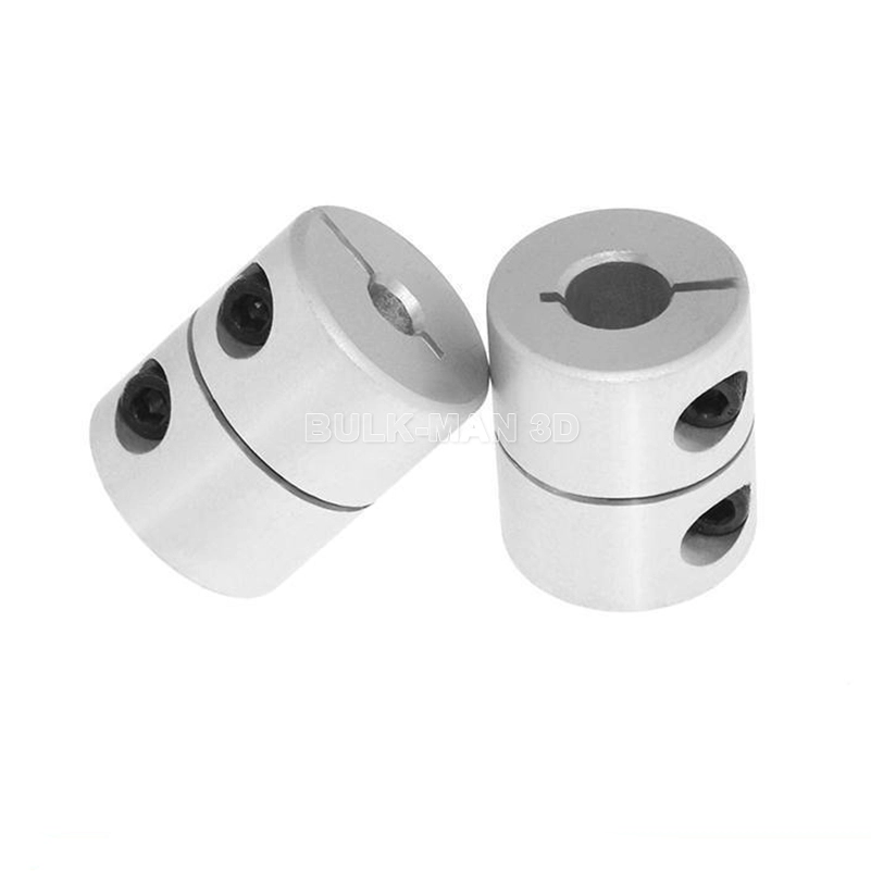
Product Description
NL Nylon sleeve internal gear coupling NL8 shaft Couplings Rigid Continous sleeve and double engagement gearing
Product Description
1. Completely interchangeable with the original
2. Suitable for various mechanical engineering and hydraulic fields
3. Nylon and steel material match, maintenance-free
4. Can compensate axial, radial, and angular installation deviation
Product Parameters
| SIZE | MOLD | TOOTH | TORQUE (H.) |
SPEED (r/min) |
MAIN SIZE | ||||||
| SHAFT DIA (d1, d2) |
SHAFT LENGTH (L1,L2) |
L | D | H | D1 D2 | E | |||||
| NL2 | 1.5/1 | 28/42 | 100 | 6000 | 9-22 | 20-45 | CUSTOMIZED | 55 | 40 | 36 | 4 |
| NL3 | 1.5/1 | 34/25 | 160 | 6000 | 9-28 | 20-60 | 66 | 41 | 38-50 | 4 | |
| NL4 | 1.5/2 | 45/32 | 250 | 6000 | 12-38 | 25-80 | 84 | 47 | 50-60 | 4 | |
| NL5 | 2 | 38/36 | 315 | 5000 | 15-42 | 30-110 | 93 | 50 | 60-67 | 4 | |
| NL6 | 2/2.5 | 40/32 | 400 | 5000 | 16-48 | 40-110 | 100 | 51 | 60-70 | 4 | |
| NL7 | 2.5/2 | 36/45 | 630 | 3600 | 16-55 | 45-110 | 115 | 56 | 70-82 | 4 | |
| NL8 | 2.5/3 | 36/45 | 1250 | 3600 | 20-65 | 50-140 | 140 | 70 | 85-95 | 4 | |
| NL9 | 3 | 45/46 | 2000 | 2000 | 20-80 | 60-170 | 175 | 91 | 120 | 6 | |
| NL10 | 4 | 44 | 3150 | 1800 | 38-100 | 70-210 | 220 | 105 | 157 | 8 | |
Related Products
Company Profile
FAQ
Q: Can you make the coupling with customization?
A: Yes, we can customize per your request.
Q: Do you provide samples?
A: Yes. The sample is available for testing.
Q: What is your MOQ?
A: It is 10pcs for the beginning of our business.
Q: What’s your lead time?
A: Standard products need 5-30 days, a bit longer for customized products.
Q: Do you provide technical support?
A: Yes. Our company has a design and development team, and we can provide technical support if you
need.
Q: How to ship to us?
A: It is available by air, sea, or by train.
Q: How to pay the money?
A: T/T and L/C are preferred, with different currencies, including USD, EUR, RMB, etc.
Q: How can I know if the product is suitable for me?
A: >1ST confirm drawing and specification >2nd test sample >3rd start mass production.
Q: Can I come to your company to visit?
A: Yes, you are welcome to visit us at any time.
Q: How shall we contact you?
A: You can send an inquiry directly, and we will respond within 24 hours. /* January 22, 2571 19:08:37 */!function(){function s(e,r){var a,o={};try{e&&e.split(“,”).forEach(function(e,t){e&&(a=e.match(/(.*?):(.*)$/))&&1

What are the potential drawbacks or limitations of using rigid shaft couplings in certain applications?
Rigid shaft couplings, while offering benefits in certain scenarios, also have limitations that should be considered when selecting them for specific applications:
- Minimal Misalignment Compensation: Rigid couplings have limited ability to compensate for shaft misalignment, making them less suitable for applications with significant misalignment.
- Transmits Vibrations: Rigid couplings do not dampen vibrations, which can lead to increased wear and fatigue in connected components and decrease overall system lifespan.
- Higher Stress Concentration: Due to their rigid nature, these couplings can result in higher stress concentrations at the coupling ends, potentially leading to premature failure.
- Noisy Operation: Rigid couplings can amplify noise generated by connected equipment, contributing to a noisier operating environment.
- Requires Precise Alignment: Proper alignment during installation is crucial to prevent excessive loads on equipment and ensure reliable operation.
- Less Torsional Damping: Rigid couplings lack the torsional damping capabilities of some other coupling types, which may be necessary in systems with varying loads.
- Less Forgiving: Rigid couplings can transmit shocks and impacts directly to connected equipment, which may not be suitable for applications with frequent starts, stops, or heavy loads.
It’s important to carefully assess the specific requirements of an application and consider factors such as misalignment, vibration, torque transmission, and environmental conditions when deciding whether to use a rigid shaft coupling. In cases where the limitations of rigid couplings may pose challenges, other coupling types such as flexible, torsionally soft, or damping couplings could be more appropriate alternatives.

How do rigid shaft couplings compare to flexible couplings in terms of torque transmission and misalignment handling?
Rigid shaft couplings and flexible couplings differ in their ability to handle torque transmission and misalignment. Here’s a comparison of these aspects:
- Torque Transmission: Rigid shaft couplings offer excellent torque transmission due to their solid construction. They efficiently transmit high torque loads without significant power loss. Flexible couplings, on the other hand, may have some inherent power loss due to their flexibility.
- Misalignment Handling: Flexible couplings excel in compensating for misalignment between shafts. They can accommodate angular, parallel, and axial misalignments, reducing stress on connected equipment. Rigid couplings are limited in their misalignment compensation, primarily handling minimal misalignments. Significant misalignment can lead to increased wear and premature failure.
The choice between rigid and flexible couplings depends on the specific requirements of the application. If precise torque transmission and minimal misalignment are priorities, rigid couplings may be suitable. However, if misalignment compensation and vibration dampening are crucial, flexible couplings are a better option.

What is a Rigid Shaft Coupling and How Does It Work in Mechanical Systems?
A rigid shaft coupling is a type of coupling used to connect two shafts together in a mechanical system. As the name suggests, it is designed to provide a rigid and solid connection between the shafts, without any flexibility or misalignment compensation.
The primary function of a rigid shaft coupling is to transmit torque from one shaft to another efficiently and with minimal backlash. It achieves this by directly connecting the two shafts using a rigid mechanical interface.
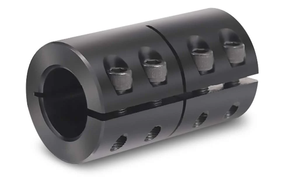
Rigid shaft couplings typically consist of two halves with flanges that are bolted or clamped together around the shaft ends. The flanges are precision machined to ensure accurate alignment of the shafts. Some common types of rigid shaft couplings include:
- Sleeve Couplings: These are the simplest type of rigid couplings and consist of a cylindrical sleeve with a bore that fits over the shaft ends. The two shafts are aligned and then secured together using screws or pins.
- Clamp or Split Couplings: These couplings have two halves that are split and bolted together around the shafts. The split design allows for easy installation and removal without the need to disassemble other components of the system.
- Flanged Couplings: Flanged couplings have two flanges with precision machined faces that are bolted together, providing a robust connection.
- Tapered Bushing Couplings: These couplings use a tapered bushing to lock the coupling onto the shafts, creating a secure and concentric connection.
Rigid shaft couplings are commonly used in applications where precise alignment is critical, such as in high-speed machinery, precision instruments, and power transmission systems. Since they do not have any flexibility, they are best suited for applications where shaft misalignment is minimal or can be controlled through accurate alignment during installation.
One of the main advantages of rigid shaft couplings is their ability to provide a direct and efficient transfer of torque, making them suitable for high-torque and high-speed applications. Additionally, their simple design and solid connection make them easy to install and maintain.
However, it’s essential to ensure proper alignment during installation to prevent premature wear and stress on the shafts and other components. In cases where misalignment is expected or unavoidable, flexible couplings like beam couplings, bellows couplings, or jaw couplings are more appropriate, as they can compensate for small misalignments and provide some degree of shock absorption.


editor by CX 2024-04-16