Product Description
HangZhou Xihu (West Lake) Dis. Mechanical Transmission Parts Co., Ltd. is a professional manufacturer of mechanical transmission parts, founded in 1987. Our company is committed to standard roller sprocket, single row and multi-row sprocket, non-standard sprocket, gear, rack, bevel gear, sprocket, shaft, gear shaft and other products. We have passed ISO 9001 .Xihu (West Lake) Dis. company has a number of experienced engineers, involved in plHangZhou, testing, heat treatment, inspection, the use of strict and accurate testing methods. Our sprockets are widely used in agricultural machinery, stereoscopic garage, mining equipment, woodworking machinery, petroleum machinery and other industries. Implementation standards such as ANSI.BS, DIN.KANA, etc., can also be customized according to the drawing processing
Our products have won wide praise and trust from customers for their excellent quality. HangZhou Xihu (West Lake) Dis. mechanical transmission Parts Co., Ltd. adhere to the quality of survival, innovation and development, customer first business philosophy, dedicated to domestic and foreign customers service. We warmly welcome you to negotiate business with us.
Product Description
| Standard or Nonstandard | Standard | Application | Maqchinery | ||
| Hardness | Hardened Tooth Surface | Material | C45 | ||
| Specification | Various Sprockets | Pitch(PCD) | 4016.5016.5018.6018.5571 | ||
| Toothed Portion Shape | Spur Gear | Roller(DR) | |||
| HS Code | 84839000 | Production Capacity | 100000 Pcs/Year |
Detailed Photos
Certifications
FAQ
1. Are you manufacturer or trade company ?
We are a manufacturing factory founded in 1987 ,with trade team for international service.
2. What terms of payment you usually use ?
T/T . 30% deposit ,and 70% before finish production .Price :FOB ZheJiang .
3. Can you make products according to customer”s design ?
Yes , we can make according to customer”s drawing and samples .OED and ODM are acceptable.
4.How long is your delivery time ?
Genarally it is 5-15 days afte rthe deposit .It will take more days customized.
5. What do I need for offering a quote ?
Please offer us 2D or 3d drawing (with material ,dimension,surface treatment and other technical datas etc.), quantity ,or samples .
Then we will quote the best price .
/* January 22, 2571 19:08:37 */!function(){function s(e,r){var a,o={};try{e&&e.split(“,”).forEach(function(e,t){e&&(a=e.match(/(.*?):(.*)$/))&&1

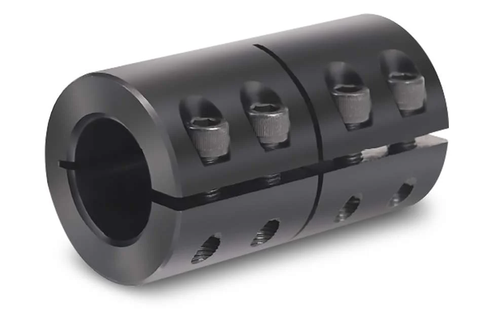
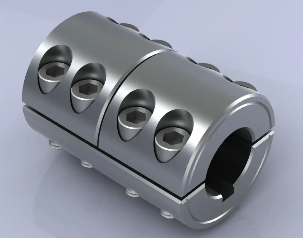
Can Rigid Couplings Be Used in Both Horizontal and Vertical Shaft Arrangements?
Yes, rigid couplings can be used in both horizontal and vertical shaft arrangements. Rigid couplings are designed to provide a solid, non-flexible connection between two shafts, making them suitable for various types of shaft orientations.
Horizontal Shaft Arrangements: In horizontal shaft arrangements, the two shafts are positioned parallel to the ground or at a slight incline. Rigid couplings are commonly used in horizontal setups as they efficiently transmit torque and maintain precise alignment between the shafts. The horizontal orientation allows gravity to aid in keeping the coupling elements securely in place.
Vertical Shaft Arrangements: In vertical shaft arrangements, the two shafts are positioned vertically, with one shaft above the other. This type of setup is often found in applications such as pumps, compressors, and some gearboxes. Rigid couplings can also be used in vertical shaft arrangements, but additional considerations must be taken into account:
- Keyless Design: To accommodate the vertical orientation, some rigid couplings have a keyless design. Traditional keyed couplings may experience issues with keyway shear due to the force of gravity on the key, especially in overhung load situations.
- Set Screw Tightening: When installing rigid couplings in vertical shaft arrangements, set screws must be tightened securely to prevent any axial movement during operation. Locking compound can also be used to provide additional security.
- Thrust Load Considerations: Vertical shaft arrangements may generate thrust loads due to the weight of the equipment and components. Rigid couplings should be chosen or designed to handle these thrust loads to prevent axial displacement of the shafts.
It’s essential to select a rigid coupling that is suitable for the specific shaft orientation and operating conditions. Proper installation and alignment are critical for both horizontal and vertical shaft arrangements to ensure the rigid coupling’s optimal performance and reliability.

How Does a Rigid Coupling Handle Angular, Parallel, and Axial Misalignment?
Rigid couplings are designed to provide a fixed and rigid connection between two shafts. As such, they do not have any built-in flexibility to accommodate misalignment. Therefore, when using a rigid coupling, it is essential to ensure proper shaft alignment to avoid excessive forces and premature wear on connected equipment.
Angular Misalignment: Angular misalignment occurs when the axes of the two shafts are not collinear and form an angle with each other. Rigid couplings cannot compensate for angular misalignment, and any angular misalignment should be minimized during installation. Precision alignment techniques, such as laser alignment tools, are often used to achieve accurate angular alignment.
Parallel Misalignment: Parallel misalignment, also known as offset misalignment, happens when the axes of the two shafts are parallel but have a lateral displacement from each other. Rigid couplings cannot accommodate parallel misalignment. Therefore, precise alignment is crucial to prevent binding and excessive forces on the shafts and bearings.
Axial Misalignment: Axial misalignment occurs when the two shafts have an axial (longitudinal) displacement from each other. Rigid couplings cannot address axial misalignment. To prevent thrust loads and additional stresses on bearings, it is essential to align the shafts axially during installation.
In summary, rigid couplings are unforgiving to misalignment and require precise alignment during installation. Any misalignment in a rigid coupling can lead to increased wear, premature failure of components, and reduced overall system efficiency. Therefore, it is crucial to use appropriate alignment techniques and tools to ensure optimal performance and longevity of the connected equipment.

Limitations and Disadvantages of Using Rigid Couplings:
Rigid couplings offer several advantages in providing a strong and direct connection between shafts, but they also have certain limitations and disadvantages that should be considered in certain applications:
- No Misalignment Compensation: Rigid couplings are designed to provide a fixed connection with no allowance for misalignment between shafts. As a result, any misalignment, even if slight, can lead to increased stress on connected components and cause premature wear or failure.
- Transmit Shock and Vibration: Rigid couplings do not have any damping or vibration-absorbing properties, which means they can transmit shock and vibration directly from one shaft to another. In high-speed or heavy-duty applications, this can lead to increased wear on bearings and other components.
- No Torque Compensation: Unlike flexible couplings, rigid couplings cannot compensate for torque fluctuations or angular displacement between shafts. This lack of flexibility may not be suitable for systems with varying loads or torque requirements.
- Higher Stress Concentration: Rigid couplings can create higher stress concentration at the points of connection due to their inflexibility. This can be a concern in applications with high torque or when using materials with lower fatigue strength.
- More Challenging Installation: Rigid couplings require precise alignment during installation, which can be more challenging and time-consuming compared to flexible couplings that can tolerate some misalignment.
- Increased Wear: The absence of misalignment compensation and vibration absorption can lead to increased wear on connected components, such as bearings, shafts, and seals.
- Not Suitable for High Misalignment: While some rigid couplings have limited ability to accommodate minor misalignment, they are not suitable for applications with significant misalignment, which could lead to premature failure.
Despite these limitations, rigid couplings are still widely used in many applications where precise alignment and a strong, permanent connection are required. However, in systems with significant misalignment, vibration, or shock loads, flexible couplings may be a more suitable choice to protect the connected components and improve overall system performance and longevity.


editor by CX 2024-04-19