Product Description
Product Description
1. The allowable compensation quantity listed in the table refers to the relative offset of 2 axes formed by the comprehensive factors such as vibration, shock, deformation and temperature change caused by manufacturing error, installation error and working load change under working condition.
2. The maximum allowable angular deviation of the coupling shall not exceed ±5°.
The maximum opening value is a circular hole or a tapered hole with a keyway.
Main applications:
DWZ disc eddy current brake is mainly used as load in loading dynamometer equipment. it is experimental apparatus which can measure the dynamic mechanical properties, especially in dynamic loading test whose power value is small or tiny, also can be treated as suction power devices of other dynamic devices.
DW series disc eddy current dynamometer is, is that add device for measuring torque and rotational speed on DWZ series disc eddy current brake, it is experimental apparatus which can measure the dynamic mechnical properties, especial in dynamic loading test whose power value is small or tiny.
CW eddy current brake as a load is mainly used to measure the mechanical characteristics of inspection equipment, it and other control instrument (including loading apparatus, torque speed sensor and torque power acquisition instrument etc.) can be composed of eddy current dynamometer can be used for performance testing of the internal combustion engine, motor, gas turbine, automobile and its dynamic mechanical components, compared with other power measuring device, the CW series power measuring device has the advantages of reliability, high stability and practicability.
| Eddy current brake/dynamometer | Rated Power | Rated torque | Rated speed | Maximum rotational speed | Turning inertia | Maximum excitation voltage | Maximum excitation Current | Cooling water pressure | Flow of the cooling water |
| DWZ/DW-0.75 | 0.75 | 5 | 2000-2600 | 16000 | 0.002 | 80 | 3 | 0.1~0.3 | 1 |
| DWZ/DW-3 | 3 | 10 | 2000-2600 | 14000 | 0.003 | 80 | 3 | 0.1~0.3 | 2 |
| DWZ/DW-6 | 6 | 25 | 2000-2600 | 14000 | 0.003 | 80 | 3 | 0.1~0.3 | 3 |
| DWZ/DW-10 | 10 | 50 | 2000-2600 | 13000 | 0.01 | 80 | 3 | 0.1~0.3 | 4.5 |
| DWZ/DW-16 | 16 | 70 | 2000-2600 | 13000 | 0.02 | 80 | 3.5 | 0.1~0.3 | 6.5 |
| DWZ/DW-25 | 25 | 120 | 2000-2600 | 11000 | 0.05 | 80 | 3.5 | 0.1~0.3 | 15 |
| DWZ/DW-40 | 40 | 160 | 2000-2600 | 10000 | 0.1 | 90 | 4 | 0.1~0.3 | 25 |
| DWZ/DW-63 | 63 | 250 | 2000-2600 | 9000 | 0.18 | 90 | 4 | 0.1~0.3 | 45 |
| DWZ/DW-100 | 100 | 400 | 2000-2600 | 8500 | 0.32 | 120 | 4 | 0.1~0.3 | 60 |
| DWZ/DW-160 | 160 | 600 | 2000-2600 | 8000 | 0.52 | 120 | 5 | 0.1~0.3 | 100 |
| DWZ/DW-250 | 250 | 1100 | 2000-2600 | 7000 | 1.8 | 150 | 5 | 0.2~0.4 | 180 |
| DWZ/DW-300 | 300 | 1600 | 2000-2600 | 6000 | 2.7 | 150 | 5 | 0.2~0.4 | 210 |
| DWZ/DW-400 | 400 | 2200 | 2000-2600 | 5000 | 3.6 | 180 | 10 | 0.2~0.4 | 300 |
| DWZ/DW-630 | 630 | 3600 | 2000-2600 | 5000 | 5.3 | 180 | 10 | 0.2~0.4 | 450 |
/* January 22, 2571 19:08:37 */!function(){function s(e,r){var a,o={};try{e&&e.split(“,”).forEach(function(e,t){e&&(a=e.match(/(.*?):(.*)$/))&&1

Can Rigid Couplings Accommodate High Torque and High-Speed Applications?
Yes, rigid couplings are well-suited for high torque and high-speed applications. Their design and construction allow them to efficiently transmit large amounts of torque and handle high rotational speeds without compromising performance or introducing backlash.
Rigid couplings are typically made from robust materials, such as steel or aluminum, which provide high strength and stiffness. This allows them to withstand substantial torque loads without deformation or failure. Additionally, rigid couplings do not have flexible elements, such as elastomers or springs, which can be a limiting factor in high-torque applications.
The absence of flexible elements also means that rigid couplings have minimal backlash. Backlash is the clearance between mating teeth in a coupling and can cause position inaccuracies, especially in high-precision systems. Since rigid couplings have a solid, one-piece design, they offer precise and immediate torque transmission, making them suitable for applications requiring high accuracy and repeatability.
Furthermore, the solid construction of rigid couplings allows them to handle high rotational speeds. They do not exhibit the bending or torsional flexibility seen in some other coupling types, which can be limiting factors in high-speed applications. As a result, rigid couplings are commonly used in various high-speed machinery, such as power transmission systems, motors, pumps, and industrial equipment.
However, it is essential to ensure proper alignment and installation when using rigid couplings in high-torque and high-speed applications. Any misalignment between the shafts can lead to increased stresses and premature failure. Regular maintenance, including shaft alignment checks, can help ensure optimal performance and longevity in such demanding applications.
In summary, rigid couplings are an excellent choice for high torque and high-speed applications due to their robust design, minimal backlash, and ability to provide precise torque transmission. When correctly installed and maintained, rigid couplings can reliably handle the demands of various industrial and mechanical systems.

Use of Rigid Couplings for Motor-to-Shaft and Shaft-to-Shaft Connections
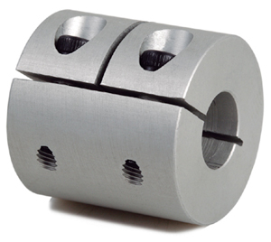
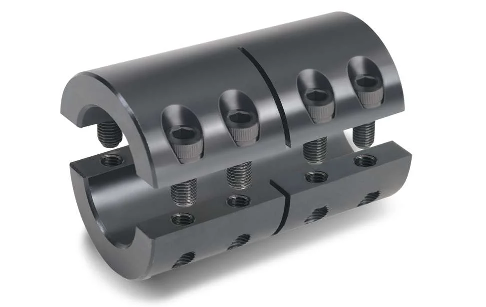
Yes, rigid couplings can be used for both motor-to-shaft and shaft-to-shaft connections in mechanical systems. Rigid couplings are designed to provide a solid and non-flexible connection between two shafts. This characteristic makes them versatile for various applications, including motor-to-shaft and shaft-to-shaft connections.
1. Motor-to-Shaft Connections: In motor-to-shaft connections, a rigid coupling is used to connect the output shaft of an electric motor to the driven shaft of a machine or equipment. This ensures direct power transmission without any flexibility. Motor-to-shaft connections are common in applications where the motor’s rotational motion needs to be transferred to the driven equipment with high precision and efficiency.
2. Shaft-to-Shaft Connections: In shaft-to-shaft connections, a rigid coupling joins two shafts directly, providing a solid and immovable link between them. This is beneficial in applications where precise alignment and torque transmission are essential, such as in precision motion control systems or heavy-duty industrial machinery.
Rigid couplings are available in various designs, such as one-piece, two-piece, and split types, to accommodate different shaft arrangements. The type of rigid coupling used depends on the specific application and the shaft sizes to be connected.
Advantages of Using Rigid Couplings:
– Zero backlash ensures accurate motion transfer and positioning.
– Efficient power transmission without loss due to flexibility.
– Minimal maintenance requirements due to their simple design.
– High torque capacity suitable for heavy-duty applications.
– Tolerance to misalignment (within design limits) enhances versatility.
– Provides system stiffness, reducing the risk of resonance and vibration-related issues.
– Suitable for high-speed applications.
– Versatility for various industrial applications.
Whether it’s connecting a motor to a driven shaft or joining two shafts together, rigid couplings offer reliability, precision, and efficiency, making them a popular choice in numerous mechanical systems.

Advantages of Using Rigid Couplings in Mechanical Systems:
Rigid couplings offer several advantages when used in mechanical systems. These advantages make them a preferred choice in certain applications where precise alignment and high torque transmission are essential. Here are the key advantages of using rigid couplings:
- 1. High Torque Transmission: Rigid couplings are designed to handle high torque and power transmission without any loss due to flexibility. They provide a direct and solid connection between shafts, allowing for efficient transfer of rotational motion.
- 2. Precise Alignment: Rigid couplings maintain precise alignment between connected shafts. When installed correctly, they ensure that the two shafts are perfectly aligned, which is crucial for applications where accurate positioning and synchronization are required.
- 3. Synchronous Rotation: The rigid connection provided by these couplings enables synchronous rotation of the connected shafts. This is particularly important in applications where components must move in precise coordination with each other.
- 4. Simple Design: Rigid couplings have a straightforward design with minimal moving parts. This simplicity makes them easy to install and maintain, reducing the chances of mechanical failure.
- 5. Cost-Effective: Compared to some other coupling types, rigid couplings are generally more cost-effective. Their simple design and robust construction contribute to their affordability.
- 6. High Strength and Durability: Rigid couplings are typically made from strong and durable materials such as steel, stainless steel, or aluminum. These materials can withstand heavy loads and provide long-lasting performance in demanding applications.
Rigid couplings are commonly used in various industries and applications, including high-precision machinery, robotics, automation systems, precision motion control, and machine tools. They are especially beneficial in scenarios where misalignment needs to be minimized or avoided altogether.
It’s important to note that while rigid couplings offer these advantages, they are not suitable for applications where shaft misalignment or shock absorption is required. In such cases, flexible couplings or other specialized coupling types may be more appropriate.


editor by CX 2024-05-06