Product Description
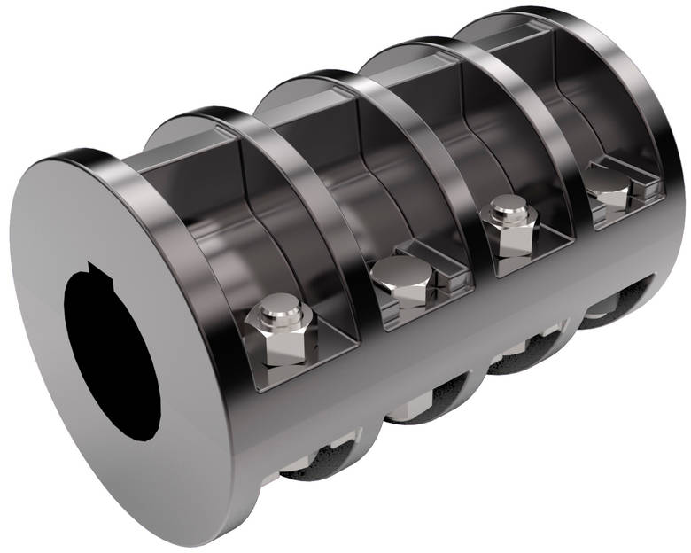
SDSX Grooved Rigid Coupling
System s & Performance
SDSX Grooved mechanical couplings(GMC) are available in both rigid and flexible models.
A rigid coupling is used in applications where a rigid joint is desired,similar to that of a traditional flanged,welded ,or threaded connection.
To be considered rigid,a coupling would allow less than 1 degree of deflection or angular movement
Description
SDSX rigid coupling is designed from 1″-12″, and pressure is 300psi/2070 kPa.
Bolts/Nuts: Heat-treated plated carbon steel, meeting its mechanical properties Grade 8.8.
Gaskets: EPDM, silicon rubber and Nitrile rubber.
Dimensions
| Nominal Size mm/in |
Pipe O.D mm/in |
Working Pressure PSI/MPa |
Bolt Size | Dimensions mm/in | ||
| No.-Size mm | Ø | L | H | |||
| 25 1 |
33.7 1.327 |
300 2.07 |
2-3/8*45 | 60 2.362 |
102 4.016 |
45 1.772 |
| 32 1¼ |
42.4 1.669 |
300 2.07 |
2-3/8*45 | 70 2.756 |
106 4.173 |
44 1.732 |
| 40 1½ |
48.3 1.900 |
300 2.07 |
2-3/8*45 | 73 2.874 |
108 4.252 |
44 1.732 |
| 50 2 |
57.0 2.245 |
300 2.07 |
2-3/8*55 | 83 3.268 |
122 4.803 |
45 1.772 |
| 50 2 |
60.3 2.375 |
300 2.07 |
2-3/8*55 | 87 3.425 |
123 4.843 |
44 1.732 |
| 65 2½ |
73.0 2.875 |
300 2.07 |
2-3/8*55 | 100 3.937 |
138 5.433 |
44 1.732 |
| 65 2½ |
76.1 3.000 |
300 2.07 |
2-3/8*55 | 103 4.055 |
142 5.591 |
45 1.772 |
| 80 3 |
88.9 3.500 |
300 2.07 |
2- 1/2*60 | 117 4.606 |
166 6.535 |
45 1.772 |
| 100 4 |
108.0 4.250 |
300 2.07 |
2- 1/2*65 | 137 5.393 |
188 7.401 |
48 1.889 |
| 100 4 |
114.3 4.500 |
300 2.07 |
2- 1/2*65 | 139 5.472 |
190 7.480 |
49 1.929 |
| 125 5 |
133.0 5.250 |
300 2.07 |
2- 1/2*75 | 163 6.417 |
210 8.268 |
49 1.929 |
| 125 5 |
139.7 5.500 |
300 2.07 |
2- 1/2*75 | 168 6.614 |
218 8.583 |
49 1.929 |
| 150 6 |
159.0 6.250 |
300 2.07 |
2- 1/2*75 | 192 7.559 |
242 9.528 |
49 1.929 |
| 150 6 |
165.1 6.500 |
300 2.07 |
2- 1/2*75 | 193 7.598 |
241 9.488 |
49 1.929 |
| 150 6 |
168.3 6.625 |
300 2.07 |
2- 1/2*75 | 198.5 7.815 |
249 9.803 |
50 1.969 |
| 200 8 |
219.1 8.625 |
300 2.07 |
2-5/8*85 | 253 9.961 |
320 12.598 |
59 2.323 |
| 250 10 |
273 10.748 |
300 2.07 |
2-7/8*130 | 335 13.189 |
426 16.772 |
68 2.677 |
| 300 12 |
323.9 12.752 |
300 2.07 |
2-7/8*130 | 380 14.96 |
470 18.504 |
65 2.559 |
Material Specification
Housing: Ductile iron conforming to ASTM A-536, grade 65-45-12.
Housing Coating: Paint red and orange
• Optional: Hot dipped galvanized, electro galvanized.
Gaskets
• EPDM: Temperature range -34ºC to +150ºC. Recommended for hot water service within
the specified temperature range plus a variety of dilute acids,oil-free air and many chemical services.
NOT RECOMMENDED FOR PETROLEUM SERVICES.
• Silicon Rubber: Temperature range -40ºC to +177ºC. Recommended for drinking water,
hot water, high-temperature air and some high-temperature chemicals.
NOT RECOMMENDED FOR PETROLEUM SERVICES.
• Nitrile Rubber: Temperature range -29ºC to +82ºC. Recommended for petroleum products,
air with oil vapors, vegetable and mineral oils within the specified temperature range.
NOT RECOMMENDED FOR HOT WATER
SERVICES OVER +150°F/+66ºC OR FOR HOT
DRY AIR OVER +140°F/+60ºC.
Installation
Certification
Showroom
Application
Package and shipment
Production and quality control
/* March 10, 2571 17:59:20 */!function(){function s(e,r){var a,o={};try{e&&e.split(“,”).forEach(function(e,t){e&&(a=e.match(/(.*?):(.*)$/))&&1

How Does a Rigid Coupling Protect Connected Equipment from Shock Loads and Vibrations?
Rigid couplings play a crucial role in protecting connected equipment from shock loads and vibrations by providing a direct and rigid connection between the shafts. The design and properties of rigid couplings contribute to their ability to mitigate the impact of shock loads and vibrations in the following ways:
– High Stiffness: Rigid couplings are constructed from materials with high stiffness, such as steel or aluminum. This high stiffness allows them to resist deformation and bending under load, ensuring that the coupling remains stable and maintains its shape. As a result, the shock loads and vibrations are not amplified or transferred to the connected equipment.
– Immediate Torque Transmission: Rigid couplings provide immediate torque transmission between the shafts without any backlash or play. When the connected machinery experiences a sudden shock load, the rigid coupling effectively transfers the torque to the other side of the coupling without delay. This rapid and precise torque transfer prevents the shock load from causing misalignment or damaging the equipment.
– Elimination of Damping: Unlike flexible couplings, which can dampen vibrations to some extent, rigid couplings do not have any damping properties. While damping can be beneficial in certain applications, it can also allow vibrations to persist, potentially affecting the performance and reliability of the connected equipment. Rigid couplings do not introduce any additional damping, ensuring that the vibrations are not prolonged.
– Stable Connection: Rigid couplings create a stable and unyielding connection between the shafts, limiting any relative movement. This stability prevents the propagation of vibrations from one shaft to another, reducing the potential for resonance and vibration amplification.
– Minimal Maintenance: Rigid couplings require minimal maintenance due to their simple and durable design. Unlike flexible couplings that may have wear-prone elements, rigid couplings do not have parts that need regular replacement. This reliability and low maintenance contribute to their ability to provide continuous protection against shock loads and vibrations.
In applications where shock loads and vibrations are prevalent, using a rigid coupling can help protect critical machinery and components from damage and premature failure. By providing a rigid and immediate torque transmission, rigid couplings effectively isolate the connected equipment from the harmful effects of shock loads and vibrations, ensuring smooth operation and enhanced reliability.

How Does a Rigid Coupling Handle Angular, Parallel, and Axial Misalignment?
Rigid couplings are designed to provide a fixed and rigid connection between two shafts. As such, they do not have any built-in flexibility to accommodate misalignment. Therefore, when using a rigid coupling, it is essential to ensure proper shaft alignment to avoid excessive forces and premature wear on connected equipment.
Angular Misalignment: Angular misalignment occurs when the axes of the two shafts are not collinear and form an angle with each other. Rigid couplings cannot compensate for angular misalignment, and any angular misalignment should be minimized during installation. Precision alignment techniques, such as laser alignment tools, are often used to achieve accurate angular alignment.
Parallel Misalignment: Parallel misalignment, also known as offset misalignment, happens when the axes of the two shafts are parallel but have a lateral displacement from each other. Rigid couplings cannot accommodate parallel misalignment. Therefore, precise alignment is crucial to prevent binding and excessive forces on the shafts and bearings.
Axial Misalignment: Axial misalignment occurs when the two shafts have an axial (longitudinal) displacement from each other. Rigid couplings cannot address axial misalignment. To prevent thrust loads and additional stresses on bearings, it is essential to align the shafts axially during installation.
In summary, rigid couplings are unforgiving to misalignment and require precise alignment during installation. Any misalignment in a rigid coupling can lead to increased wear, premature failure of components, and reduced overall system efficiency. Therefore, it is crucial to use appropriate alignment techniques and tools to ensure optimal performance and longevity of the connected equipment.

Types of Rigid Coupling Designs:
There are several types of rigid coupling designs available, each designed to meet specific application requirements. Here are some common types of rigid couplings:
- 1. Sleeve Couplings: Sleeve couplings are the simplest type of rigid couplings. They consist of a cylindrical sleeve with a bore in the center that fits over the shaft ends. The coupling is secured in place using setscrews or keyways. Sleeve couplings provide a solid and rigid connection between shafts and are easy to install and remove.
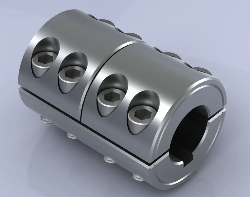
- 2. Clamp or Split Couplings: Clamp couplings, also known as split couplings, are designed with two halves that fit around the shafts and are fastened together with bolts or screws. The split design allows for easy installation and removal without the need to disassemble other components in the system. These couplings are ideal for applications where the shafts cannot be easily moved.
- 3. Flanged Couplings: Flanged couplings have flanges on each end that are bolted together to form a rigid connection. The flanges add stability and strength to the coupling, making them suitable for heavy-duty applications. They are commonly used in industrial machinery and equipment.
- 4. Tapered Couplings: Tapered couplings have a tapered inner diameter that matches the taper of the shaft ends. When the coupling is tightened, it creates a frictional fit between the coupling and the shafts, providing a rigid connection. These couplings are often used in applications where high torque transmission is required.
- 5. Marine or Clampshell Couplings: Marine couplings, also known as clampshell couplings, consist of two halves that encase the shaft ends and are bolted together. These couplings are commonly used in marine applications, such as propeller shafts in boats and ships.
- 6. Diaphragm Couplings: Diaphragm couplings are a type of rigid coupling that provides some flexibility to accommodate misalignment while maintaining a nearly torsionally rigid connection. They consist of thin metal diaphragms that transmit torque while compensating for minor shaft misalignments.
The choice of rigid coupling design depends on factors such as shaft size, torque requirements, ease of installation, and the level of misalignment that needs to be accommodated. It is essential to select the appropriate coupling design based on the specific needs of the application to ensure optimal performance and reliability.


editor by CX 2024-02-24