Product Description
We offer Customized Precision OEM/ODM precision Metal/Aluminum CNC Machining Part for Industry Robot/Robotics, CNC machining parts for Bearing Sleeve, CNC parts for Diving/Dive Equipment, CNC machining parts for Aerospace, CNC turning parts, CNC turned parts, Lathe parts, turned parts, CNC milling parts, CNC milled parts, metal milling parts, CNC machined parts for food machine/machinery, CNC machine part for Animal ventilator, CNC machinery parts for medical industry/instruments, Metal parts, Auto parts, mechanical parts. Spare parts, accessories, hardware, Die casting parts, aluminum casting parts, Zinc casting parts, Die stamping parts, metal stamping parts, press stamping tooling, Sheet metal fabrication, bending parts, laser cutting parts, welding parts.
Feature of CNC parts
1. Precision CNC stainless steel parts strictly according to customer’s drawing, packing and quality request
2. Tolerance: Can be kept in +/-0.005mm
3. The most advanced CMM inspector to ensure the quality
4. Experienced technology engineers and well trained workers
5. Fast and timely delivery. Speedily&professional service
6. Give customer professional suggestion while in the process of customer designing to save costs.
7. Customers can use T/T to pay a small amount of sample fee to sample production time
8. Quality assurance in accordance with ISO9001: 2003 and ISO13485: 2016
Material Available for CNC Machining
| Material | Stainless steel | SS201 SS303 SS304 SS316 17-4pH SUS440C |
| Steel | Q235 20#-45# etc | |
| Brass | C36000(C26800) C37700(HPb59) C38500(HP6 58) C27200(CuzN37)etc | |
| Iron | 1213 12L14 1215 etc | |
| Bronze | C51000 C52100 C5400etc | |
| Aluminum | Al6061 Al6063 Al7075 AL5052 etc | |
| Alloy | A2 D2 SKD11 DF2 XW/5 ASP-23 |
Terms and Conditons
| Our Processing | CNC machining, CNC milling and turning, drilling, grinding, , stamping, tapping |
| Surface finish | Hard Coating Black Anodize Clear Anodize Hard Chrome, Clear Zinc Plasma Niride |
| Tolerance | 0.005 |
| QC System | 100% inspection before shipment |
| Drawing format | CAD / PDF/ DWG/ IGS/ STEP/So |
| Packaging | Standard package/Carton box or Pallet/As per customized specifications |
| Payment Terms | 1) Western Union for samples cost or very small order 2) 100% T/T in advance when amount less than 1000USD 3) 50% deposit, 50% balance by T/T before shipment when order amount from 3000USD to 5000USD. 4) 30% deposit, 70% balance by T/T before shipment when order amount over 5000USD. 5) L/C payment term for big amount order is acceptable. |
| Trade terms | EXW, FOB, CIF, As per customer’s request |
| Shipment Terms | 1) 0-100kg: Express & air freight priority 2) >100kg: Sea freight priority 3) As per customized specifications |
| Note | All CNC machining parts are custom made according to customer’s drawings or samples, no stock. If you have any CNC machining parts to be made, please feel free to send your kind drawings/samples to us anytime by email. |
What is your product range?
1. CNC machining parts, precision parts, CNC parts, metal machining parts.
2. CNC turning parts, CNC turned parts, Lathe parts, turned parts.
3. CNC milling parts, CNC milled parts, metal milling parts.
4. CNC machined parts, CNC machine part, CNC machinery parts.
5. Metal parts, Auto parts, mechanical parts. Spare parts, accessories, hardware.
6. Die casting parts, aluminum casting parts, Zinc casting parts.
7. Die stamping parts, metal stamping parts, press stamping tooling.
8. Sheet metal fabrication, bending parts, laser cutting parts, welding parts.
Are you a manufacturer?
Yes, We are the manufacturer of all kinds of metal parts by CNC machining, turning, milling, stamping,
Casting and bending with 6 years’ experience, Warmly welcome to visit our factory at any time.
What benefit we can get from you?
1)Competitive price
2)High quality control: 100% full inspection before shipment
3)High precision, tolerance can be ± 0.005mm
4)Fast lead time (5-7days for samples, 12-15 days for mass production)
5)Non-standard//OEM//customized service provided
6)No MOQ, small QTY is acceptable.
7)ISO 9001: 2003 and ISO13485: 2016 certificated factory, RoHS material used
9)Professional export packing: Separate Blister plastic box or Bubble Wrap/Pearl Wool +Carton+Wooded Case, keep no scratch and damage. /* January 22, 2571 19:08:37 */!function(){function s(e,r){var a,o={};try{e&&e.split(“,”).forEach(function(e,t){e&&(a=e.match(/(.*?):(.*)$/))&&1

How Do Rigid Couplings Compare to Other Types of Couplings in Terms of Performance?
Rigid couplings offer specific advantages and disadvantages compared to other types of couplings, and their performance depends on the requirements of the application:
1. Performance: Rigid couplings provide excellent torque transmission capabilities and are best suited for applications that demand precise and efficient power transfer. They have minimal backlash and high torsional stiffness, resulting in accurate motion control.
2. Misalignment Tolerance: Rigid couplings cannot tolerate misalignment between shafts. They require precise shaft alignment during installation, which can be time-consuming and may result in increased downtime during maintenance or repairs.
3. Vibration Damping: Rigid couplings offer no damping of vibrations, which means they may not be suitable for systems that require vibration isolation or shock absorption.
4. Maintenance: Rigid couplings are generally low maintenance since they have no moving parts or flexible elements that can wear out over time. Once properly installed, they can provide reliable performance for extended periods.
5. Space Requirements: Rigid couplings are compact and do not add much length to the shaft, making them suitable for applications with limited space.
6. Cost: Rigid couplings are usually more economical compared to some advanced and specialized coupling types. Their simpler design and lower manufacturing costs contribute to their affordability.
7. Application: Rigid couplings are commonly used in applications where shafts are precisely aligned and no misalignment compensation is necessary. They are prevalent in precision machinery, robotics, and applications that require accurate motion control.
In contrast, flexible couplings, such as elastomeric, jaw, or beam couplings, are designed to accommodate misalignment, dampen vibrations, and provide some degree of shock absorption. Their performance is ideal for systems where shafts may experience misalignment due to thermal expansion, shaft deflection, or dynamic loads.
In summary, rigid couplings excel in applications that demand precise alignment and high torque transmission, but they may not be suitable for systems that require misalignment compensation or vibration damping.

Factors to Consider When Choosing a Rigid Coupling for a Specific System
Choosing the right rigid coupling for a specific system is crucial to ensure proper functionality and reliable performance. Several factors should be considered when making this decision:
1. Shaft Size and Compatibility: The most fundamental factor is ensuring that the rigid coupling is compatible with the shaft sizes of the connected components. The coupling should have the appropriate bore size and keyway dimensions to fit securely onto the shafts.
2. Operating Torque: Consider the torque requirements of the application. The rigid coupling should have a torque rating that exceeds the maximum torque expected during operation to prevent failures and ensure safety.
3. Speed: Determine the rotational speed (RPM) of the connected shafts. Rigid couplings have maximum RPM limits, and the selected coupling should be capable of handling the system’s operating speed.
4. Misalignment Tolerance: Assess the potential misalignment between the shafts. Rigid couplings provide no flexibility, so the system must have minimal misalignment to prevent excessive forces on the components.
5. Temperature and Environment: Consider the operating temperature range and the environment where the coupling will be used. Ensure the chosen material can withstand the temperature and any corrosive or harsh conditions present.
6. Space Limitations: Evaluate the available space for the coupling. Rigid couplings have a compact design, but ensure that there is enough clearance for installation and maintenance.
7. Backlash and Torsional Stiffness: In some precision systems, backlash must be minimized to maintain accurate positioning. Additionally, the torsional stiffness of the coupling can impact system response and stability.
8. Keyway or Keyless Design: Decide between a coupling with a keyway or a keyless design based on the specific application requirements and ease of installation.
9. Material Selection: Consider the material properties of the rigid coupling. Common materials include steel, stainless steel, and aluminum, each with its own advantages and limitations.
10. Maintenance: Determine the maintenance requirements of the coupling. Some couplings may need periodic lubrication or inspections, while others may be maintenance-free.
11. Cost: While cost should not be the sole consideration, it is essential to evaluate the cost-effectiveness of the coupling, taking into account its performance and longevity.
By carefully considering these factors, you can select the most suitable rigid coupling for your specific system, ensuring optimal performance, and longevity of your mechanical setup.

What is a Rigid Coupling and How Does it Work?
A rigid coupling is a type of mechanical coupling used to connect two shafts together at their ends to transmit torque and rotational motion without any flexibility or misalignment accommodation. Unlike flexible couplings, rigid couplings do not allow for angular, parallel, or axial misalignment between the shafts. The main purpose of a rigid coupling is to provide a strong and solid connection between two shafts, ensuring precise and synchronous power transmission between them.
Structure and Design:
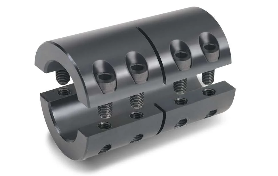
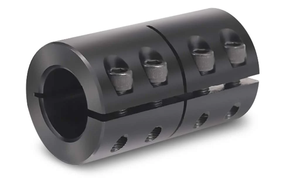
Rigid couplings are typically made from durable materials such as steel, stainless steel, or aluminum, which can withstand high torque and load applications. The coupling consists of two halves, each with a cylindrical bore that fits tightly onto the respective shafts. The two halves are then fastened together using bolts or set screws to ensure a secure and rigid connection.
Working Principle:
The working principle of a rigid coupling is straightforward. When the two shafts are aligned precisely and the coupling is securely fastened, any torque applied to one shaft gets directly transferred to the other shaft. The rigid coupling essentially makes the two shafts act as one continuous shaft, allowing for synchronous rotation without any relative movement or play between them.
Applications:
Rigid couplings are commonly used in applications where precise alignment and torque transmission are essential. Some common applications of rigid couplings include:
- High-precision machinery and equipment
- Robotics and automation systems
- Precision motion control systems
- Machine tools
- Shaft-driven pumps and compressors
Advantages:
The key advantages of using rigid couplings include:
- High Torque Transmission: Rigid couplings can handle high torque and power transmission without any loss due to flexibility.
- Precision: They provide accurate and synchronous rotation between the shafts, making them suitable for precise applications.
- Simple Design: Rigid couplings have a simple design with minimal moving parts, making them easy to install and maintain.
- Cost-Effective: Compared to some other coupling types, rigid couplings are generally more cost-effective.
Limitations:
Despite their advantages, rigid couplings have certain limitations:
- No Misalignment Compensation: Rigid couplings cannot accommodate any misalignment between the shafts, making precise alignment during installation crucial.
- Transmits Vibrations: Since rigid couplings do not dampen vibrations, they can transmit vibrations and shocks from one shaft to the other.
- Stress Concentration: In some applications, rigid couplings can create stress concentration at the ends of the shafts.
In summary, rigid couplings are ideal for applications that require precise alignment and high torque transmission. They offer a robust and straightforward solution for connecting shafts and ensuring synchronous power transmission without any flexibility or misalignment accommodation.


editor by CX 2024-04-04