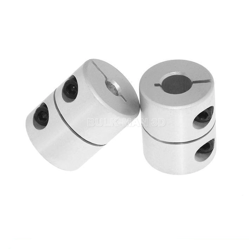
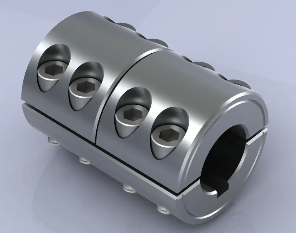
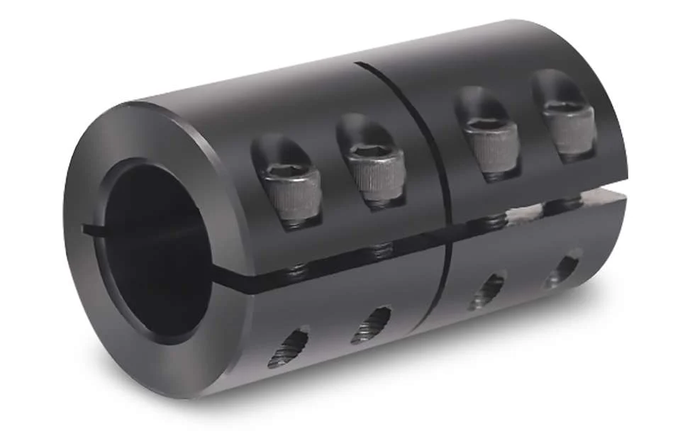
Product Description
Hot sale: low noise,no leakage, no additional cost for rigid shaft coupling magnetic couple motor couplings
Introduction of rigid shaft coupling magnetic couple motor couplings
Magnetic shaft coupling is a new kind of coupling, which connects motor and machine by permanent magnetic force.
They are consisted of external rotor, internal rotor and isolating covers.
They work in the sealed magnetic drive pumps, which transporting volatile, flammable, explosive and toxic solutions with no leakage.
These magnetic shaft couplings can be used to connect gear pumps , screw pumps, centrifugal pumps, etc. with all types of electric motor or gear box.
Magnetic shaft coupling are widely used in various industries and fields, such as chemical, papermaking, foodstuff, pharmacy, and so on.
Advantages of rigid shaft coupling magnetic couple motor couplings
» Elimination of fluid leakage from the pump shaft.
» Vibrations are not transmitted to the pump.
» No maintenance required for magnetic couplings.
» Using magnetic couplings allows use of standard pumps without expensive mechanical seals.
» No additional cost for purchasing mechanical seal spare parts and maintenance.
Technical drawing of rigid shaft coupling magnetic couple motor couplings
Specification of rigid shaft coupling magnetic couple motor couplings
| Item | Internal Rotor(mm) | External Rotor(mm) | Isolating Covering(mm) | |||||||||||||||||
| A | B | C | D | E | F | G | Shaft Pin | H | I | J | L | N | M | P | Q | R | S | T | U | |
| GME03-3LM00 | Φ35 | – | Φ10 | 26 | – | 18 | – | M6X12 | Φ42 | Φ60 | Φ50 | 46 | 6-M4 | Φ40 | Φ50 | 4-Φ5.4 | Φ38 | Φ60 | 6 | 6 |
| GME03-5MM00 | Φ42 | – | Φ12 | 27 | 4 | 18 | 13.8 | M6X16 | Φ49 | Φ72 | Φ60 | 46 | 4-Φ6.7 | Φ52 | Φ60 | 4-Φ6.7 | Φ44 | Φ74 | 8 | 8 |
| GME03-16LM00 | Φ56 | – | Φ12 | 45 | 4 | 25 | 13.8 | M6X16 | Φ63 | Φ89 | Φ80 | 75 | 6-M5 | Φ70 | Φ75 | 4-Φ6.7 | Φ58 | Φ89 | 8 | 8 |
| GME03-16LM01 | Φ56 | – | Φ12 | 45 | 4 | 25 | 13.8 | M6X16 | Φ63 | Φ89 | Φ80 | 75 | 4-M5 | Φ70 | Φ75 | 4-Φ6.7 | Φ58 | Φ89 | 6 | 10 |
| GME03-16MM00 | Φ56 | – | Φ12 | 45 | 4 | 25 | 13.8 | M6X16 | Φ63 | Φ89 | Φ80 | 75 | 6-M5 | Φ70 | Φ75 | 4-Φ6.7 | Φ58 | Φ89 | 8 | 8 |
| GME03-22LM00 | Φ88 | – | Φ20 | 29 | 6 | 25 | 22.8 | M8X20 | Φ97 | Φ122 | Φ110 | 70 | 8-M6 | Φ98 | Φ108 | 6-Φ6.7 | Φ91 | Φ122 | 8 | 8 |
| GME03-30LM00 | Φ88 | – | Φ20 | 48 | 6 | 30 | 22.8 | M8X20 | Φ97 | Φ122 | Φ110 | 81 | 8-M6 | Φ98 | Φ108 | 6-Φ6.7 | Φ91 | Φ122 | 8 | 8 |
| GME03-40LM00 | Φ101 | – | Φ25 | 49 | 8 | 28 | 28.3 | M10X20 | Φ109 | Φ140 | Φ124 | 83 | 8-M8 | Φ110 | Φ126 | 8-Φ6.7 | Φ103 | Φ140 | 12 | 6 |
| GME03-50LM00 | Φ107 | – | Φ20 | 70 | 6 | 30 | 22.8 | M6X16 | Φ113.4 | Φ145 | Φ135 | 80 | 4-M6 | Φ126 | Φ133 | 12-Φ8.7 | Φ109 | Φ153 | 12 | 15 |
| GME03-65LM00 | Φ101 | – | Φ25 | 77 | 8 | 45 | 28.3 | M10X20 | Φ109 | Φ140 | Φ124 | 111 | 8-M8 | Φ110 | Φ126 | 8-Φ6.7 | Φ103 | Φ140 | 12 | 6 |
| GME03-80LM00 | Φ106 | – | Φ32 | 65 | 10 | 21 | 36.5 | M6X25 | Φ115 | Φ145 | Φ135 | 82 | 4-M6 | Φ127 | Φ135 | 6-Φ8.7 | Φ110 | Φ153 | 13 | 18 |
| GME03-80LM00 | Φ141 | Φ92 | Φ40 | 65 | 12 | 45 | 43.3 | M12X25 | Φ152 | Φ180 | Φ168 | 100 | 8-M8 | Φ154 | Φ164 | 8-Φ6.7 | Φ145 | Φ180 | 12 | 8 |
| GME03-100LM00 | Φ131 | Φ82 | Φ32 | 80 | 10 | 24.5 | 35.3 | M8X35 | Φ139 | Φ170 | Φ160 | 100 | 4-M6 | Φ152 | Φ158 | 8-Φ8.7 | Φ133 | Φ178 | 14 | 21 |
| GME03-110LH00 | Φ141 | Φ92 | Φ40 | 85 | 10 | 50 | 43.3 | M12X25 | Φ152 | Φ184 | Φ168 | 115 | 12-M8 | Φ156 | Φ164 | 12-Φ6.7 | Φ145 | Φ180 | 12 | 3 |
| GME03-110LM00 | Φ141 | Φ92 | Φ35 | 80 | 10 | 55 | 38.3 | M12X25 | Φ152 | Φ180 | Φ168 | 115 | 12-M8 | Φ154 | Φ164 | 12-Φ6.7 | Φ145 | Φ180 | 12 | 3 |
| GME03-140LM00 | Φ141 | Φ92 | Φ40 | 110 | 12 | 80 | 43.3 | M12X25 | Φ152 | Φ190 | Φ170 | 145 | 12-M10 | Φ154 | Φ164 | 12-Φ6.7 | Φ145 | Φ180 | 12 | 3 |
| GME03-180LM00 | Φ141 | Φ92 | Φ40 | 140 | 12 | 95 | 43.3 | M12X25 | Φ152 | Φ190 | Φ170 | 175 | 12-M10 | Φ154 | Φ164 | 12-Φ6.7 | Φ145 | Φ180 | 12 | 3 |
| GME03-220LM00 | Φ141 | Φ92 | Φ48 | 160 | 14 | 110 | 51.8 | M12X25 | Φ152 | Φ190 | Φ170 | 195 | 12-M10 | Φ154 | Φ164 | 12-Φ6.7 | Φ145 | Φ180 | 12 | 3 |
| GME03-300LM00 | Φ162 | – | Φ65 | 100 | 18 | 60 | 69.4 | Φ170 | Φ198 | Φ188 | 123 | 12-M6 | Φ180 | Φ192 | 12-Φ11 | Φ163.5 | Φ218 | 16 | 10 | |
| GME03-400LH00 | Φ195 | – | Φ70 | 127 | 20 | 107 | 79.9 | M12X25 | Φ203 | Φ234 | Φ222 | 152 | 6-M6 | Φ212 | Φ164 | 12-Φ11 | Φ198 | Φ278 | 16 | 22 |
Application of rigid shaft coupling magnetic couple motor couplings
The ability to hermetically separate 2 areas whilst continuing to transmit mechanical power from one to the other makes these couplings ideal for applications where prevention of cross contamination is essential. For instance: hydraulic sectors, dosing systems, compressors, sterilizers, industrial ovens, biotechnology, subsea equipment, pharmaceutical industry, chemical industry, food industry, generators and mixers.
Operation principles of rigid shaft coupling magnetic couple motor couplings
The magnetic coupling works by using the power generated by permanent magnets. No external power supply is needed. These are permanent magnets not electro magnets.
Packing Method of rigid shaft coupling magnetic couple motor couplings
Double strength corrugated Carton and Wood case Sea Packing.
/* January 22, 2571 19:08:37 */!function(){function s(e,r){var a,o={};try{e&&e.split(“,”).forEach(function(e,t){e&&(a=e.match(/(.*?):(.*)$/))&&1

What are the potential drawbacks or limitations of using rigid shaft couplings in certain applications?
Rigid shaft couplings, while offering benefits in certain scenarios, also have limitations that should be considered when selecting them for specific applications:
- Minimal Misalignment Compensation: Rigid couplings have limited ability to compensate for shaft misalignment, making them less suitable for applications with significant misalignment.
- Transmits Vibrations: Rigid couplings do not dampen vibrations, which can lead to increased wear and fatigue in connected components and decrease overall system lifespan.
- Higher Stress Concentration: Due to their rigid nature, these couplings can result in higher stress concentrations at the coupling ends, potentially leading to premature failure.
- Noisy Operation: Rigid couplings can amplify noise generated by connected equipment, contributing to a noisier operating environment.
- Requires Precise Alignment: Proper alignment during installation is crucial to prevent excessive loads on equipment and ensure reliable operation.
- Less Torsional Damping: Rigid couplings lack the torsional damping capabilities of some other coupling types, which may be necessary in systems with varying loads.
- Less Forgiving: Rigid couplings can transmit shocks and impacts directly to connected equipment, which may not be suitable for applications with frequent starts, stops, or heavy loads.
It’s important to carefully assess the specific requirements of an application and consider factors such as misalignment, vibration, torque transmission, and environmental conditions when deciding whether to use a rigid shaft coupling. In cases where the limitations of rigid couplings may pose challenges, other coupling types such as flexible, torsionally soft, or damping couplings could be more appropriate alternatives.

What are the maintenance requirements for rigid shaft couplings to extend their lifespan?
Rigid shaft couplings are mechanical components used to connect two shafts and transmit torque between them. While rigid couplings are known for their durability and minimal maintenance needs, proper care and maintenance can further extend their lifespan and ensure optimal performance. Here are key maintenance considerations:
- Lubrication: Some rigid couplings, especially those with moving parts like set screws, may require periodic lubrication to reduce friction and wear. Use appropriate lubricants as recommended by the manufacturer.
- Visual Inspection: Regularly inspect the coupling for signs of wear, corrosion, or damage. Look for cracks, dents, or any other abnormalities that could affect its performance. Address any issues promptly.
- Tightening Fasteners: If the rigid coupling is secured using fasteners such as set screws or bolts, ensure they are tightened to the manufacturer’s specifications. Loose fasteners can lead to misalignment and reduced coupling effectiveness.
- Alignment Check: Periodically check the alignment of the connected shafts. Misalignment can lead to increased stress on the coupling and premature wear. Realign the shafts if necessary.
- Coupling Integrity: Make sure the coupling is securely fastened and properly seated on both shafts. Any looseness or improper fitting can lead to vibrations and wear.
- Cleanliness: Keep the coupling and surrounding area clean from dirt, debris, and contaminants. Foreign particles can lead to increased wear and reduced performance.
- Environmental Factors: Consider the operating environment. If the coupling is exposed to harsh conditions, such as extreme temperatures or corrosive substances, take appropriate measures to protect the coupling’s surfaces and materials.
- Replacement of Worn Parts: If any components of the coupling show significant wear or damage, consider replacing them as per the manufacturer’s recommendations. This can prevent further issues and maintain coupling integrity.
- Manufacturer Guidelines: Always follow the maintenance recommendations provided by the coupling manufacturer. They can provide specific guidelines based on the coupling’s design and materials.
Proper maintenance practices not only extend the lifespan of rigid shaft couplings but also contribute to the overall reliability and efficiency of the connected machinery. Regular inspections and maintenance can help identify potential issues early, preventing costly downtime and repairs.
It’s important to note that maintenance requirements can vary based on the specific design and material of the rigid coupling. Consulting the manufacturer’s documentation and seeking professional advice can help establish a suitable maintenance schedule tailored to the coupling’s characteristics and the application’s demands.

What is a Rigid Shaft Coupling and How Does It Work in Mechanical Systems?
A rigid shaft coupling is a type of coupling used to connect two shafts together in a mechanical system. As the name suggests, it is designed to provide a rigid and solid connection between the shafts, without any flexibility or misalignment compensation.
The primary function of a rigid shaft coupling is to transmit torque from one shaft to another efficiently and with minimal backlash. It achieves this by directly connecting the two shafts using a rigid mechanical interface.
Rigid shaft couplings typically consist of two halves with flanges that are bolted or clamped together around the shaft ends. The flanges are precision machined to ensure accurate alignment of the shafts. Some common types of rigid shaft couplings include:
- Sleeve Couplings: These are the simplest type of rigid couplings and consist of a cylindrical sleeve with a bore that fits over the shaft ends. The two shafts are aligned and then secured together using screws or pins.
- Clamp or Split Couplings: These couplings have two halves that are split and bolted together around the shafts. The split design allows for easy installation and removal without the need to disassemble other components of the system.
- Flanged Couplings: Flanged couplings have two flanges with precision machined faces that are bolted together, providing a robust connection.
- Tapered Bushing Couplings: These couplings use a tapered bushing to lock the coupling onto the shafts, creating a secure and concentric connection.
Rigid shaft couplings are commonly used in applications where precise alignment is critical, such as in high-speed machinery, precision instruments, and power transmission systems. Since they do not have any flexibility, they are best suited for applications where shaft misalignment is minimal or can be controlled through accurate alignment during installation.
One of the main advantages of rigid shaft couplings is their ability to provide a direct and efficient transfer of torque, making them suitable for high-torque and high-speed applications. Additionally, their simple design and solid connection make them easy to install and maintain.
However, it’s essential to ensure proper alignment during installation to prevent premature wear and stress on the shafts and other components. In cases where misalignment is expected or unavoidable, flexible couplings like beam couplings, bellows couplings, or jaw couplings are more appropriate, as they can compensate for small misalignments and provide some degree of shock absorption.


editor by CX 2024-05-09