Product Description
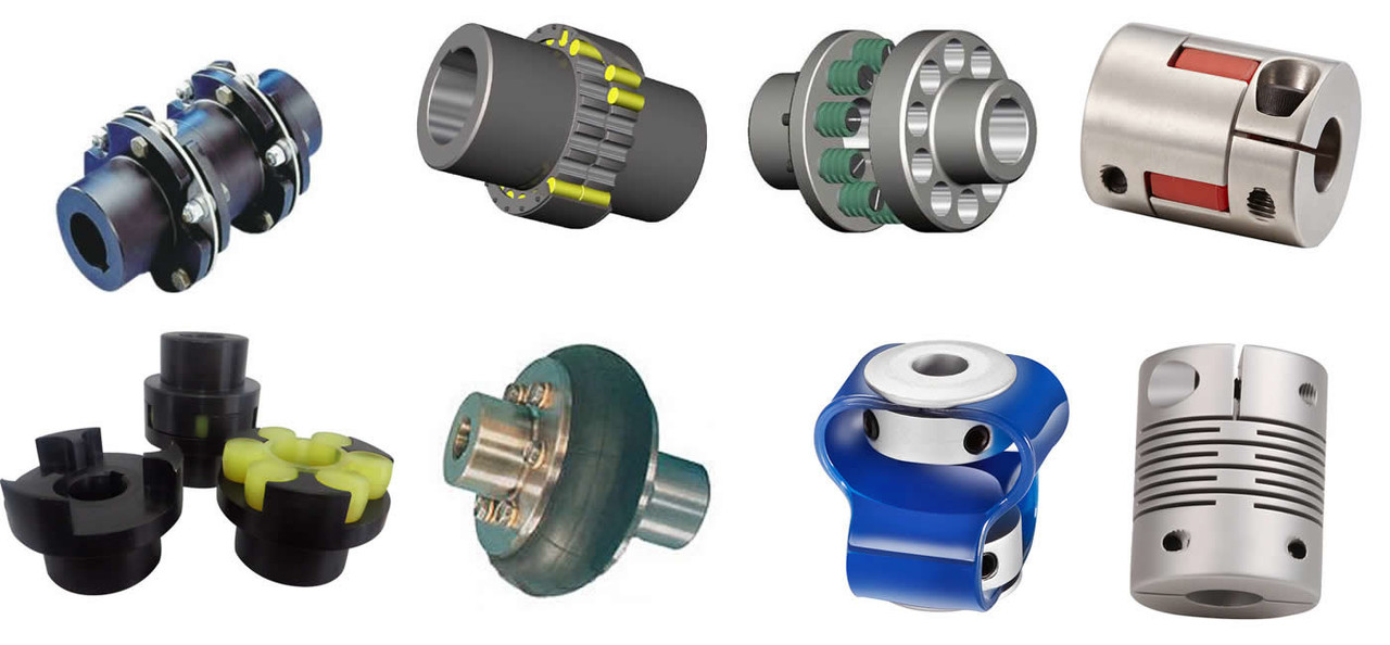
JAW coupling,
1. The couplings offer a range of hub and element selection to meet different demands.
2. They can absorb shock and cater for incidental misalignment and damp out small amplitude vibrations.
3. NBR, Urethane, Hytrel elements.
4. Customized requirement is available.
| Element material | Rubber | Urethane | Hytrel | Brozen |
/* January 22, 2571 19:08:37 */!function(){function s(e,r){var a,o={};try{e&&e.split(“,”).forEach(function(e,t){e&&(a=e.match(/(.*?):(.*)$/))&&1

Understanding the Torque and Misalignment Capabilities of Shaft Couplings
Shaft couplings play a critical role in transmitting torque and accommodating misalignment between rotating shafts in mechanical power transmission systems. Understanding their torque and misalignment capabilities is essential for selecting the right coupling for a specific application. Here’s an overview:
Torque Transmission:
The torque capacity of a shaft coupling refers to its ability to transmit rotational force from one shaft to another. It is typically specified in torque units, such as Nm (Newton-meters) or lb-ft (pound-feet). The coupling’s torque capacity depends on its design, size, and material.
When selecting a coupling, it’s crucial to ensure that its torque capacity meets or exceeds the torque requirements of the application. Overloading a coupling beyond its torque capacity can lead to premature failure or damage to the coupling and connected equipment.
Misalignment Compensation:
Shaft misalignment can occur due to various factors, including thermal expansion, manufacturing tolerances, or foundation settling. Misalignment puts additional stress on the coupling and connected components, potentially leading to increased wear and reduced efficiency.
Shaft couplings are designed to compensate for different types of misalignment:
- Angular Misalignment: Occurs when the shafts are not parallel and have an angle between them.
- Parallel Misalignment: Occurs when the shafts are not collinear, resulting in axial displacement.
- Radial Misalignment: Occurs when the shafts have lateral displacement but remain parallel.
The coupling’s misalignment capabilities are specified in terms of angular and axial misalignment values, usually in degrees or millimeters. Different coupling designs can accommodate varying degrees of misalignment, and the choice depends on the specific application and operating conditions.
Flexible Couplings:
Flexible couplings, such as elastomeric or jaw couplings, offer good misalignment compensation. They can handle a combination of angular, parallel, and axial misalignments. However, their torque capacity may be limited compared to rigid couplings.
Rigid Couplings:
Rigid couplings, such as clamp or sleeve couplings, have high torque transmission capabilities but offer minimal misalignment compensation. They are best suited for applications where shafts are well-aligned and precise torque transmission is critical.
Torsional Stiffness:
Another factor to consider is the coupling’s torsional stiffness, which determines how much torsional deflection or twist occurs under load. Some applications, like precision systems, may require couplings with high torsional stiffness to maintain accurate positioning and avoid torsional backlash.
By understanding the torque and misalignment capabilities of shaft couplings, engineers can make informed decisions when selecting a coupling to ensure efficient power transmission and reliable performance in their mechanical systems.
“`
Comparing Shaft Couplings with Other Types of Couplings in Performance
Shaft couplings are essential components in mechanical power transmission systems, and their performance characteristics vary depending on the coupling type. Let’s compare shaft couplings with other common types of couplings:
1. Shaft Couplings:
Shaft couplings come in various designs, including flexible and rigid couplings. They are widely used in a broad range of applications due to their ability to transmit torque and accommodate misalignments between rotating shafts. Flexible shaft couplings, with elastomeric or metallic elements, offer good misalignment compensation and damping characteristics. Rigid couplings, on the other hand, provide precise torque transmission and are ideal for applications where shafts are well-aligned.
2. Gear Couplings:
Gear couplings are robust and designed for heavy-duty applications. They consist of two external gear hubs with internal gear teeth that mesh together. Gear couplings can handle high torque, high-speed, and angular misalignment. They are often used in demanding industries such as steel, mining, and paper manufacturing.
3. Grid Couplings:
Grid couplings feature a flexible grid element between the two halves of the coupling. They provide excellent shock absorption and misalignment compensation. Grid couplings are commonly used in pumps, compressors, and other industrial machinery.
4. Disc Couplings:
Disc couplings utilize flexible metallic discs to transmit torque and compensate for misalignment. They offer high torsional stiffness, making them suitable for applications requiring precise motion control, such as robotics and CNC machines.
5. Jaw Couplings:
Jaw couplings consist of two hubs with elastomeric spider inserts. They are easy to install, have good misalignment capabilities, and offer electrical isolation between shafts. Jaw couplings are widely used in light to medium-duty applications.
6. Oldham Couplings:
Oldham couplings have three discs—two outer discs with slots and a central disc with a tongue that fits into the slots. They provide excellent angular misalignment compensation while maintaining constant velocity between shafts. Oldham couplings are commonly used in printing machines and conveyors.
7. Beam Couplings:
Beam couplings are made from a single piece of flexible material with spiral cuts. They offer good misalignment compensation and torsional flexibility, making them suitable for precision equipment like encoders and servo motors.
The choice of coupling depends on the specific requirements of the application, including torque, speed, misalignment compensation, environmental conditions, and space limitations. Each coupling type has its strengths and limitations, and selecting the right coupling is crucial to ensure optimal performance and reliability in the mechanical system.
“`
Best Practices for Installing a Shaft Coupling for Optimal Performance
Proper installation of a shaft coupling is crucial for ensuring optimal performance and preventing premature wear or failure. Follow these best practices to install a shaft coupling correctly:
1. Shaft Alignment:
Ensure that both the driving and driven shafts are properly aligned before installing the coupling. Misalignment can lead to increased stress on the coupling and other connected components, reducing efficiency and causing premature wear. Use alignment tools, such as dial indicators or laser alignment systems, to achieve accurate shaft alignment.
2. Cleanliness:
Before installation, clean the shaft ends and the coupling bore thoroughly. Remove any dirt, debris, or residue that could interfere with the coupling’s fit or cause misalignment.
3. Lubrication:
Apply the recommended lubricant to the coupling’s contact surfaces, such as the bore and shaft ends. Proper lubrication ensures smooth installation and reduces friction during operation.
4. Correct Fit:
Ensure that the coupling is the correct size and type for the application. Use couplings with the appropriate torque and speed ratings to match the equipment’s requirements.
5. Fastening:
Use the recommended fastening methods, such as set screws or keyways, to securely attach the coupling to the shafts. Make sure the fasteners are tightened to the manufacturer’s specifications to prevent loosening during operation.
6. Spacer or Adapter:
If required, use a spacer or adapter to properly position the coupling on the shafts and maintain the desired distance between the driving and driven components.
7. Avoid Shaft Damage:
Be careful during installation to avoid damaging the shaft ends, especially when using set screws or other fastening methods. Shaft damage can lead to stress concentrations and eventual failure.
8. Check Runout:
After installation, check the coupling’s runout using a dial indicator to ensure that it rotates smoothly and without wobbling. Excessive runout can indicate misalignment or improper fit.
9. Periodic Inspection:
Regularly inspect the coupling and its components for signs of wear, misalignment, or damage. Perform routine maintenance as recommended by the manufacturer to prevent issues from worsening over time.
10. Follow Manufacturer’s Guidelines:
Always follow the manufacturer’s installation instructions and guidelines. Different types of couplings may have specific installation requirements that need to be adhered to for optimal performance and safety.
By following these best practices, you can ensure that your shaft coupling is installed correctly, maximizing its efficiency and reliability in your mechanical power transmission system.
“`

editor by CX 2024-04-16