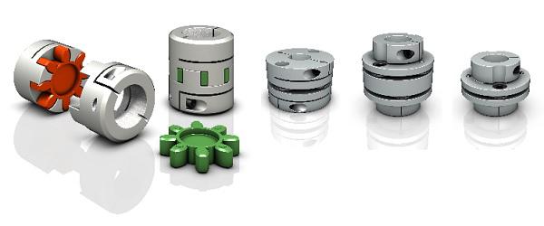
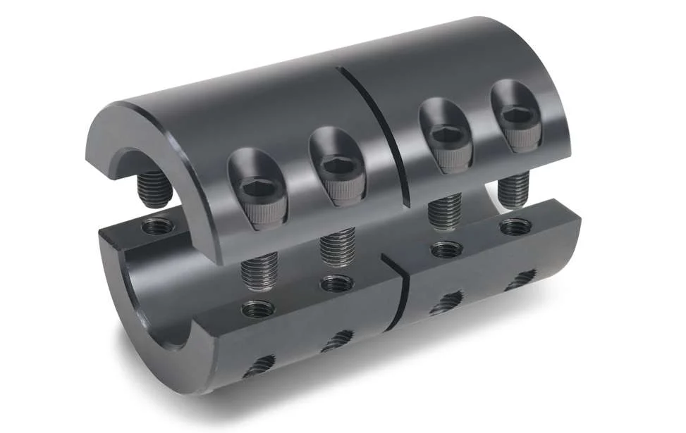
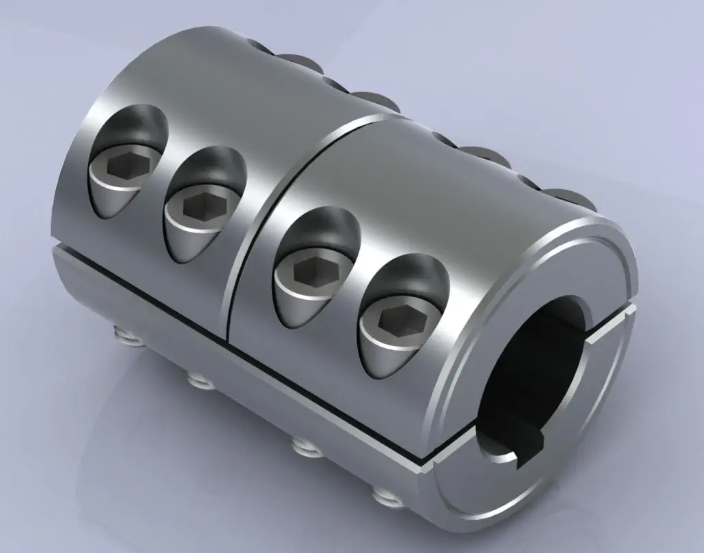
Product Description
Product Description
Coupling Deatails
Name: High precision plum blossom
coupling Model: LM-Material: Aviation Aluminum Alloy
Working temperature: -40 ° C ~ 100 ° C
Support customization: Factory direct sales support customization.
Features:
1.Intermediate Elastomer Connection-Absorbs vibration, compensates for radial, angular, and axial 2.misalignment
3.Oil resistance and electrical insulation
4.Clockwise and counterclockwise rotation characteristics are identical-there are 3 different hardness 5.elastomer
6.Fixation by clamping screw.
|
Model parameter |
ΦD |
L |
LF |
LP |
F |
M |
Tightening screw torque |
|
(N.M) |
|||||||
|
GF-14X22 |
14 |
22 |
14.3 |
6.6 |
3.8 |
M 3 |
0.7 |
|
GF-20X25 |
20 |
25 |
16.7 |
8.6 |
4 |
M 3 |
0.7 |
|
GF-20X30 |
20 |
30 |
19.25 |
8.6 |
5.3 |
M 4 |
1.7 |
|
GF-25X30 |
25 |
30 |
20.82 |
11.6 |
5.6 |
M 4 |
1.7 |
|
GF-25X34 |
25 |
34 |
22.82 |
11.6 |
5.6 |
M 4 |
1.7 |
|
GF-30X35 |
30 |
35 |
23 |
11.5 |
5.75 |
M 4 |
1.7 |
|
GF-30X40 |
30 |
40 |
25.6 |
11.5 |
10 |
M 4 |
1.7 |
|
GF-40X50 |
40 |
50 |
32.1 |
14.5 |
10 |
M 5 |
4 |
|
GF-40X55 |
40 |
55 |
34.5 |
14.5 |
10 |
M 5 |
4 |
|
GF-40X66 |
40 |
66 |
40 |
14.5 |
12.75 |
M 5 |
4 |
|
GF-55X49 |
55 |
49 |
32 |
16.1 |
13.5 |
M 6 |
8.4 |
|
GF-55X78 |
55 |
78 |
46.4 |
16.1 |
15.5 |
M 6 |
8.4 |
|
GF-65X80 |
65 |
80 |
48.5 |
17.3 |
18.1 |
M 8 |
10.5 |
|
GF-65X90 |
65 |
90 |
53.5 |
17.3 |
18.1 |
M 8 |
10.5 |
Product Parameters
Detailed Photos
/* January 22, 2571 19:08:37 */!function(){function s(e,r){var a,o={};try{e&&e.split(“,”).forEach(function(e,t){e&&(a=e.match(/(.*?):(.*)$/))&&1
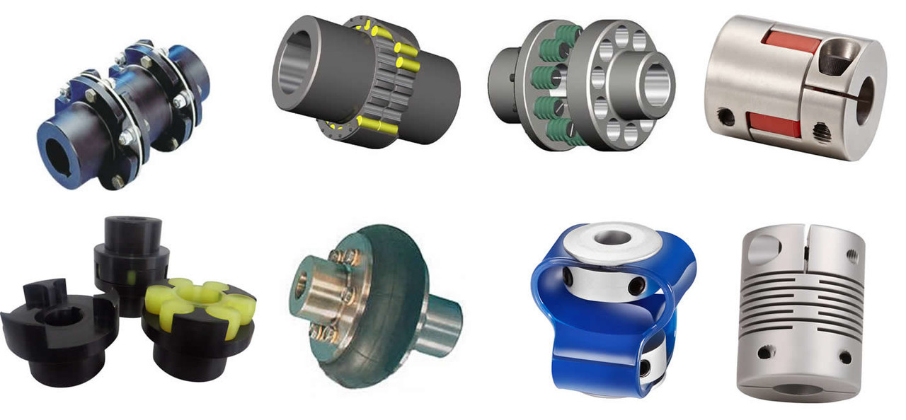
Understanding the Torque and Misalignment Capabilities of Shaft Couplings
Shaft couplings play a critical role in transmitting torque and accommodating misalignment between rotating shafts in mechanical power transmission systems. Understanding their torque and misalignment capabilities is essential for selecting the right coupling for a specific application. Here’s an overview:
Torque Transmission:
The torque capacity of a shaft coupling refers to its ability to transmit rotational force from one shaft to another. It is typically specified in torque units, such as Nm (Newton-meters) or lb-ft (pound-feet). The coupling’s torque capacity depends on its design, size, and material.
When selecting a coupling, it’s crucial to ensure that its torque capacity meets or exceeds the torque requirements of the application. Overloading a coupling beyond its torque capacity can lead to premature failure or damage to the coupling and connected equipment.
Misalignment Compensation:
Shaft misalignment can occur due to various factors, including thermal expansion, manufacturing tolerances, or foundation settling. Misalignment puts additional stress on the coupling and connected components, potentially leading to increased wear and reduced efficiency.
Shaft couplings are designed to compensate for different types of misalignment:
- Angular Misalignment: Occurs when the shafts are not parallel and have an angle between them.
- Parallel Misalignment: Occurs when the shafts are not collinear, resulting in axial displacement.
- Radial Misalignment: Occurs when the shafts have lateral displacement but remain parallel.
The coupling’s misalignment capabilities are specified in terms of angular and axial misalignment values, usually in degrees or millimeters. Different coupling designs can accommodate varying degrees of misalignment, and the choice depends on the specific application and operating conditions.
Flexible Couplings:
Flexible couplings, such as elastomeric or jaw couplings, offer good misalignment compensation. They can handle a combination of angular, parallel, and axial misalignments. However, their torque capacity may be limited compared to rigid couplings.
Rigid Couplings:
Rigid couplings, such as clamp or sleeve couplings, have high torque transmission capabilities but offer minimal misalignment compensation. They are best suited for applications where shafts are well-aligned and precise torque transmission is critical.
Torsional Stiffness:
Another factor to consider is the coupling’s torsional stiffness, which determines how much torsional deflection or twist occurs under load. Some applications, like precision systems, may require couplings with high torsional stiffness to maintain accurate positioning and avoid torsional backlash.
By understanding the torque and misalignment capabilities of shaft couplings, engineers can make informed decisions when selecting a coupling to ensure efficient power transmission and reliable performance in their mechanical systems.
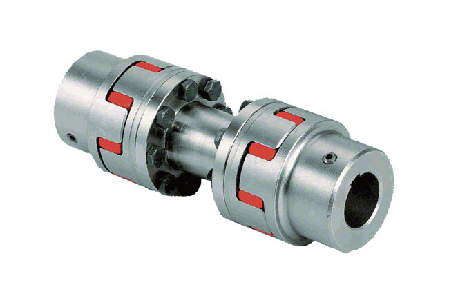
“`
Do Shaft Couplings Require Regular Maintenance, and if so, What Does it Involve?
Yes, shaft couplings do require regular maintenance to ensure their optimal performance, extend their service life, and prevent unexpected failures. The maintenance frequency may vary based on factors such as the coupling type, application, operating conditions, and the manufacturer’s recommendations. Here’s what regular maintenance for shaft couplings typically involves:
1. Visual Inspection:
Regularly inspect the coupling for signs of wear, damage, or misalignment. Check for cracks, corrosion, and worn-out elastomeric elements (if applicable). Look for any abnormal movement or rubbing between the coupling components during operation.
2. Lubrication:
If the shaft coupling requires lubrication, follow the manufacturer’s guidelines for the appropriate lubricant type and frequency. Lubrication helps reduce friction, wear, and noise in the coupling.
3. Alignment Check:
Monitor shaft alignment periodically. Misalignment can lead to premature coupling failure and damage to connected equipment. Make adjustments as needed to keep the shafts properly aligned.
4. Torque Check:
For bolted couplings, periodically check the torque on the bolts to ensure they remain securely fastened. Loose bolts can lead to misalignment and reduce coupling performance.
5. Replace Worn Components:
If any coupling components show signs of wear or damage beyond acceptable limits, replace them promptly with genuine replacement parts from the manufacturer.
6. Environmental Considerations:
In harsh environments with exposure to chemicals, moisture, or extreme temperatures, take additional measures to protect the coupling, such as applying corrosion-resistant coatings or using special materials.
7. Monitoring Coupling Performance:
Implement a monitoring system to track coupling performance and detect any changes or abnormalities early on. This could include temperature monitoring, vibration analysis, or other condition monitoring techniques.
8. Professional Inspection:
Periodically have the coupling and connected machinery inspected by qualified professionals to identify any potential issues that may not be apparent during regular inspections.
By adhering to a regular maintenance schedule and taking proactive measures to address potential issues, you can ensure that your shaft couplings operate reliably and efficiently throughout their service life, minimizing downtime and improving overall system performance.
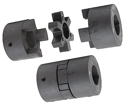
“`
Diagnosing and Fixing Common Issues with Shaft Couplings
Regular inspection and maintenance of shaft couplings are essential to detect and address common issues that may arise during operation. Here are steps to diagnose and fix some common coupling problems:
1. Abnormal Noise or Vibration:
If you notice unusual noise or excessive vibration during equipment operation, it may indicate misalignment, wear, or damage in the coupling. Check for any visible signs of damage, such as cracks or deformations, and inspect the coupling for proper alignment.
Diagnosis:
Use a vibration analysis tool to measure the vibration levels and identify the frequency of the abnormal vibrations. This can help pinpoint the source of the problem.
Fix:
If misalignment is the cause, adjust the coupling to achieve proper alignment between the shafts. Replace any damaged or worn coupling components, such as spiders or elastomeric inserts, as needed.
2. Excessive Heat:
Feeling excessive heat on the coupling during operation can indicate friction, improper lubrication, or overload conditions.
Diagnosis:
Inspect the coupling and surrounding components for signs of rubbing, lack of lubrication, or overloading.
Fix:
Ensure proper lubrication of the coupling, and check for any interference between the coupling and adjacent parts. Address any overloading issues by adjusting the equipment load or using a coupling with a higher torque capacity.
3. Shaft Movement:
If you observe axial or radial movement in the connected shafts, it may indicate wear or improper installation of the coupling.
Diagnosis:
Check the coupling’s set screws, keyways, or other fastening methods to ensure they are secure and not causing the shaft movement.
Fix:
If the coupling is worn or damaged, replace it with a new one. Ensure proper installation and use appropriate fastening methods to secure the coupling to the shafts.
4. Sheared Shear Pin:
In shear pin couplings, a sheared shear pin indicates overloading or shock loads that exceeded the coupling’s torque capacity.
Diagnosis:
Inspect the shear pin for damage or breakage.
Fix:
Replace the sheared shear pin with a new one of the correct specifications. Address any overloading issues or adjust the equipment to prevent future shearing.
5. Coupling Wear:
Regular wear is normal for couplings, but excessive wear may lead to decreased performance and increased misalignment.
Diagnosis:
Inspect the coupling components for signs of wear, such as worn elastomeric elements or damaged teeth.
Fix:
Replace the worn or damaged components with new ones of the appropriate specifications.
Remember, regular maintenance and periodic inspection are key to diagnosing issues early and preventing severe problems. Always follow the manufacturer’s recommendations for maintenance and replacement schedules to ensure the proper functioning and longevity of the shaft coupling.
“`

editor by CX 2024-05-06
China Best Sales Machinery Part Roller Chain Coupling Aluminum Case with Sprockets Shaft Flexible Coupling KC6018
Product Description
FAQ
Q:Is your company a trading company or a manufacturer?
A: We have our own factory.
Q:How long does the lead time take?
A: If the goods are in stock, it is generally 1-2 days; if the goods are not in stock, it is 5-10 days, depending on the quantity.
Q: Can I order shaft bore couplings that are not listed in the catalog?)(Additional machining service for coupling shaft hole
A:Of course.In addition, the recommended dimensional tolerance for the applicable shaft diameter is H7.
Q: How to handle when the received parts are of poor quality?
A:If there is any non-conformity of the product, please contact us immediately, we will check the problem in the first time, and rework or repair.
Q: Why choose XingHe Precision Transmission ?
A:As a professional manufacturer of coupling , we possess a skillful team of workers and designers To provide our customers with first-class services.
/* January 22, 2571 19:08:37 */!function(){function s(e,r){var a,o={};try{e&&e.split(“,”).forEach(function(e,t){e&&(a=e.match(/(.*?):(.*)$/))&&1
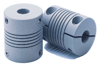
Exploring the Use of Elastomeric Materials in Flexible Shaft Couplings
Elastomeric materials play a crucial role in the design and function of flexible shaft couplings. These materials, commonly known as elastomers, are rubber-like substances that exhibit high elasticity and flexibility. They are widely used in various types of flexible couplings due to their unique properties and benefits:
1. Damping and Vibration Absorption:
Elastomeric materials have excellent damping characteristics, meaning they can absorb and dissipate vibrations and shocks. This property is particularly useful in applications where vibration control is essential to protect sensitive equipment and improve overall system performance.
2. Misalignment Compensation:
Flexible shaft couplings with elastomeric elements can accommodate different types of misalignments, including angular, parallel, and radial misalignments. The elasticity of the material allows for limited movement between the shafts while still transmitting torque efficiently.
3. Torsional Flexibility:
Elastomers offer torsional flexibility, which allows them to twist and deform under torque loads. This feature helps to minimize torsional stresses and torsional backlash, making them suitable for applications requiring precise motion control.
4. Shock and Impact Resistance:
Due to their high resilience, elastomers can withstand sudden shocks and impacts without permanent deformation. This property makes them ideal for use in machinery subjected to varying loads or rapid changes in torque.
5. No Lubrication Requirement:
Elastomeric couplings are often maintenance-free because the elastomer material does not require additional lubrication. This reduces maintenance costs and simplifies the overall system upkeep.
6. Electric Isolation:
In certain applications, elastomeric materials can provide electrical isolation between the driving and driven components. This can help prevent the transmission of electrical currents or static charges through the coupling.
7. Corrosion Resistance:
Many elastomers used in couplings are resistant to corrosion, making them suitable for use in challenging environments where exposure to chemicals or moisture is a concern.
8. Easy Installation:
Elastomeric couplings are often designed for ease of installation and replacement. Their flexibility allows for simple and quick assembly onto the shafts without the need for special tools or complex procedures.
Given these advantages, elastomeric materials are popular choices for various flexible shaft couplings, including jaw couplings, tire couplings, and spider couplings. However, it is essential to select the right elastomer material based on the specific application requirements, such as temperature range, chemical compatibility, and torque capacity.
“`
Temperature and Speed Limits for Different Shaft Coupling Types
The temperature and speed limits of shaft couplings vary depending on the materials and design of the coupling. Manufacturers provide specific guidelines and ratings for each coupling type. Below are general temperature and speed limits for some common shaft coupling types:
1. Elastomeric Couplings:
Elastomeric couplings, such as jaw couplings and tire couplings, typically have temperature limits ranging from -40°C to 100°C (-40°F to 212°F). The speed limits for elastomeric couplings are generally up to 5,000 RPM, but some designs may allow higher speeds.
2. Metallic Couplings:
Metallic couplings, like gear couplings and disc couplings, can handle a wider temperature range, typically from -50°C to 200°C (-58°F to 392°F). The speed limits for metallic couplings vary based on the size and design, but they can range from 3,000 RPM to over 10,000 RPM.
3. Grid Couplings:
Grid couplings have temperature limits similar to metallic couplings, ranging from -50°C to 200°C (-58°F to 392°F). The speed limits for grid couplings are typically in the range of 3,000 to 5,000 RPM.
4. Oldham Couplings:
Oldham couplings usually have temperature limits from -30°C to 100°C (-22°F to 212°F) and speed limits ranging from 1,000 to 5,000 RPM.
5. Beam Couplings:
Beam couplings generally have temperature limits from -40°C to 120°C (-40°F to 248°F) and speed limits between 5,000 to 10,000 RPM.
6. Fluid Couplings:
Fluid couplings are suitable for a wide range of temperatures, often from -50°C to 300°C (-58°F to 572°F). The speed limits depend on the size and design of the fluid coupling but can extend to several thousand RPM.
It’s important to note that these are general guidelines, and the actual temperature and speed limits may vary based on the specific coupling manufacturer, material quality, and application requirements. Always refer to the manufacturer’s documentation and technical specifications for accurate and up-to-date temperature and speed limits for a particular shaft coupling model.
“`
Diagnosing and Fixing Common Issues with Shaft Couplings
Regular inspection and maintenance of shaft couplings are essential to detect and address common issues that may arise during operation. Here are steps to diagnose and fix some common coupling problems:
1. Abnormal Noise or Vibration:
If you notice unusual noise or excessive vibration during equipment operation, it may indicate misalignment, wear, or damage in the coupling. Check for any visible signs of damage, such as cracks or deformations, and inspect the coupling for proper alignment.
Diagnosis:
Use a vibration analysis tool to measure the vibration levels and identify the frequency of the abnormal vibrations. This can help pinpoint the source of the problem.
Fix:
If misalignment is the cause, adjust the coupling to achieve proper alignment between the shafts. Replace any damaged or worn coupling components, such as spiders or elastomeric inserts, as needed.
2. Excessive Heat:
Feeling excessive heat on the coupling during operation can indicate friction, improper lubrication, or overload conditions.
Diagnosis:
Inspect the coupling and surrounding components for signs of rubbing, lack of lubrication, or overloading.
Fix:
Ensure proper lubrication of the coupling, and check for any interference between the coupling and adjacent parts. Address any overloading issues by adjusting the equipment load or using a coupling with a higher torque capacity.
3. Shaft Movement:
If you observe axial or radial movement in the connected shafts, it may indicate wear or improper installation of the coupling.
Diagnosis:
Check the coupling’s set screws, keyways, or other fastening methods to ensure they are secure and not causing the shaft movement.
Fix:
If the coupling is worn or damaged, replace it with a new one. Ensure proper installation and use appropriate fastening methods to secure the coupling to the shafts.
4. Sheared Shear Pin:
In shear pin couplings, a sheared shear pin indicates overloading or shock loads that exceeded the coupling’s torque capacity.
Diagnosis:
Inspect the shear pin for damage or breakage.
Fix:
Replace the sheared shear pin with a new one of the correct specifications. Address any overloading issues or adjust the equipment to prevent future shearing.
5. Coupling Wear:
Regular wear is normal for couplings, but excessive wear may lead to decreased performance and increased misalignment.
Diagnosis:
Inspect the coupling components for signs of wear, such as worn elastomeric elements or damaged teeth.
Fix:
Replace the worn or damaged components with new ones of the appropriate specifications.
Remember, regular maintenance and periodic inspection are key to diagnosing issues early and preventing severe problems. Always follow the manufacturer’s recommendations for maintenance and replacement schedules to ensure the proper functioning and longevity of the shaft coupling.
“`

editor by CX 2024-04-30
China best CNC Aluminum Elastic Rubber Spider Jaw Shaft Coupler GF14*22 20*25 25*30 40*50 Shaft Flexible Coupling Ball Screw Plum Coupling
Product Description
Product Description
Coupling Deatails
Name: High precision plum blossom
coupling Model: LM-Material: Aviation Aluminum Alloy
Working temperature: -40 ° C ~ 100 ° C
Support customization: Factory direct sales support customization.
Features:
1.Intermediate Elastomer Connection-Absorbs vibration, compensates for radial, angular, and axial 2.misalignment
3.Oil resistance and electrical insulation
4.Clockwise and counterclockwise rotation characteristics are identical-there are 3 different hardness 5.elastomer
6.Fixation by clamping screw.
|
Model parameter |
ΦD |
L |
LF |
LP |
F |
M |
Tightening screw torque |
|
(N.M) |
|||||||
|
GF-14X22 |
14 |
22 |
14.3 |
6.6 |
3.8 |
M 3 |
0.7 |
|
GF-20X25 |
20 |
25 |
16.7 |
8.6 |
4 |
M 3 |
0.7 |
|
GF-20X30 |
20 |
30 |
19.25 |
8.6 |
5.3 |
M 4 |
1.7 |
|
GF-25X30 |
25 |
30 |
20.82 |
11.6 |
5.6 |
M 4 |
1.7 |
|
GF-25X34 |
25 |
34 |
22.82 |
11.6 |
5.6 |
M 4 |
1.7 |
|
GF-30X35 |
30 |
35 |
23 |
11.5 |
5.75 |
M 4 |
1.7 |
|
GF-30X40 |
30 |
40 |
25.6 |
11.5 |
10 |
M 4 |
1.7 |
|
GF-40X50 |
40 |
50 |
32.1 |
14.5 |
10 |
M 5 |
4 |
|
GF-40X55 |
40 |
55 |
34.5 |
14.5 |
10 |
M 5 |
4 |
|
GF-40X66 |
40 |
66 |
40 |
14.5 |
12.75 |
M 5 |
4 |
|
GF-55X49 |
55 |
49 |
32 |
16.1 |
13.5 |
M 6 |
8.4 |
|
GF-55X78 |
55 |
78 |
46.4 |
16.1 |
15.5 |
M 6 |
8.4 |
|
GF-65X80 |
65 |
80 |
48.5 |
17.3 |
18.1 |
M 8 |
10.5 |
|
GF-65X90 |
65 |
90 |
53.5 |
17.3 |
18.1 |
M 8 |
10.5 |
Product Parameters
Detailed Photos
/* January 22, 2571 19:08:37 */!function(){function s(e,r){var a,o={};try{e&&e.split(“,”).forEach(function(e,t){e&&(a=e.match(/(.*?):(.*)$/))&&1
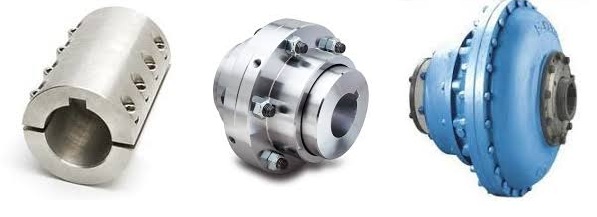
Can Shaft Couplings Compensate for Angular, Parallel, and Axial Misalignments?
Yes, shaft couplings are designed to compensate for different types of misalignments between rotating shafts in mechanical power transmission systems. They can handle the following types of misalignments:
- Angular Misalignment: This occurs when the shafts are not parallel and have an angle between them. Flexible couplings, such as elastomeric, beam, or Oldham couplings, can accommodate angular misalignments by allowing slight angular movement between the shafts while transmitting torque.
- Parallel Misalignment: This happens when the shafts are not collinear, resulting in axial displacement. Flexible couplings with lateral flexibility, like elastomeric or bellows couplings, can handle parallel misalignment by allowing limited lateral movement between the shafts.
- Radial Misalignment: Radial misalignment occurs when the shafts have lateral displacement but remain parallel. Flexible couplings, such as jaw or grid couplings, can absorb radial misalignment by permitting some lateral deflection while transmitting torque.
It is essential to note that while shaft couplings can compensate for misalignments to some extent, they do have their limits. The magnitude of misalignment they can handle depends on the type and design of the coupling. Exceeding the specified misalignment capabilities of a coupling can lead to premature wear, reduced efficiency, and possible coupling failure.
Therefore, when selecting a shaft coupling for an application, it is crucial to consider the expected misalignment and choose a coupling that can accommodate the anticipated misalignment range. Additionally, maintaining proper alignment through regular maintenance and periodic inspections is essential to ensure the coupling’s optimal performance and extend its service life.
“`
Explaining the Concept of Backlash and How It Affects Shaft Coupling Performance
Backlash is the angular movement or play between the mating components of a mechanical system when the direction of motion is reversed. In the context of shaft couplings, backlash refers to the free rotational movement between the connected shafts before the coupling transmits torque from one shaft to the other.
Backlash occurs in certain coupling designs that have features allowing relative movement between the coupling’s mating parts. Common coupling types that may exhibit some degree of backlash include elastomeric couplings (such as jaw couplings), gear couplings, and Oldham couplings.
How Backlash Affects Shaft Coupling Performance:
1. Loss of Precision: In applications requiring precise motion control, backlash can lead to inaccuracies and reduced positional accuracy. For example, in CNC machines or robotics, any rotational play due to backlash can result in positioning errors and decreased machining or movement precision.
2. Reversal Impact: When a reversing load is applied to a coupling, the presence of backlash can lead to a brief period of rotational play before the coupling re-engages, causing a momentary jolt or impact. This impact can lead to increased stress on the coupling and connected components, potentially reducing their lifespan.
3. Dynamic Response: Backlash can affect the dynamic response of the mechanical system. In systems requiring rapid acceleration or deceleration, the initial play due to backlash may create a delay in torque transmission, affecting the system’s responsiveness.
4. Noise and Vibration: Backlash can cause noise and vibration in the system, leading to increased wear and potential fatigue failure of components.
5. Misalignment Compensation: In some flexible coupling designs, a certain amount of backlash is intentionally incorporated to allow for misalignment compensation. While this is a beneficial feature, excessive backlash can compromise the coupling’s performance.
Minimizing Backlash:
Manufacturers often design couplings with specific features to minimize backlash. For instance, some gear couplings employ crowned gear teeth to reduce clearance, while elastomeric couplings may have preloaded elastomeric elements. Precision couplings like zero-backlash or torsionally rigid couplings are engineered to eliminate or minimize backlash for applications requiring high accuracy and responsiveness.
When selecting a coupling, it’s essential to consider the application’s specific requirements regarding precision, speed, reversing loads, and misalignment compensation, as these factors will determine the acceptable level of backlash for optimal performance.
“`
Types of Shaft Couplings and Their Applications in Various Industries
Shaft couplings come in various types, each designed to meet specific application requirements and address different types of misalignment. Here are some common types of shaft couplings and their applications in various industries:
1. Jaw Couplings:
Applications: Jaw couplings are widely used in power transmission applications, including conveyor systems, pumps, compressors, and industrial machinery. They are suitable for moderate torque requirements and provide good misalignment compensation.
2. Gear Couplings:
Applications: Gear couplings are used in heavy-duty industrial applications such as steel mills, paper mills, and mining equipment. They offer high torque capacity and can handle significant misalignments.
3. Disc Couplings:
Applications: Disc couplings are commonly used in precision machinery and automation systems, such as printing presses, machine tools, and robotics. They provide excellent torsional stiffness and are ideal for applications requiring precise positioning.
4. Grid Couplings:
Applications: Grid couplings are used in various industrial applications, including fans, pumps, and compressors. They offer high torque capacity and good shock absorption.
5. Oldham Couplings:
Applications: Oldham couplings are used in applications requiring high misalignment compensation, such as stepper motor drives and motion control systems.
6. Diaphragm Couplings:
Applications: Diaphragm couplings are used in critical applications that demand high torque transmission accuracy, such as aerospace, medical equipment, and semiconductor manufacturing.
7. Elastomeric Couplings:
Applications: Elastomeric couplings, like spider couplings, find applications in general industrial machinery, HVAC systems, and conveyor systems. They provide damping properties and flexibility to accommodate misalignments.
8. Torsionally Rigid Couplings:
Applications: Torsionally rigid couplings are used in applications requiring precise torque transmission, such as precision machining equipment and high-speed spindles.
9. Fluid Couplings:
Applications: Fluid couplings are used in heavy machinery and drivetrains, such as mining equipment, crushers, and marine propulsion systems. They provide smooth acceleration and dampening of shock loads.
10. Magnetic Couplings:
Applications: Magnetic couplings are used in applications where hermetic sealing is required, such as chemical processing, pumps, and mixers. They allow for torque transmission without direct physical contact.
The selection of the appropriate shaft coupling type depends on factors such as torque requirements, speed, misalignment, operating conditions, and the specific needs of the application. Using the right coupling ensures efficient power transmission, protects equipment from misalignment-related issues, and enhances the overall reliability and performance of industrial machinery and systems.
“`

editor by CX 2024-04-25
China Good quality Machinery Part Roller Chain Coupling Aluminum Case with Sprockets Shaft Flexible Coupling Kc 4012-10020
Product Description
Product Description
The roller chain coupling is a flexible coupling of amazingly simple construction. It consists of a combination of 1 coupling chain and a pair of coupling sprockets. Flexible and strong, the roller chain coupling is suitable for a wide range of coupling applications.
Roller chain coupling can used for the environment which with high temperature, wet and dirty conditions. It is not suitable for the occasion which is in high speed and with strong impact load. Roller chain coupling should working with excellent lubrication and protection cover conditions.
The common chain coupling includes double roller chain coupling, single row roller chain coupling, tooth shape chain coupling, nylon chain coupling. Its scale is compact and its weight is light. But roller chain coupling don’t have high requirement to installation precision.
Generally speaking, it is usually in long service life. Production line equipment for various kinds of frozen food and dehydrated vegetables should transport by stainless steel chain. Roller chains are widely applied to household, industrial and agricultural machinery, includes conveyor, drawing machine, printing machine, automobile, motorcycle and bicycle.
Main Features
1.Simple structure,easy assembly and disassembly.
2.Light weight,and long service life.
3.Have a certain ability to compensate for installation less precision.
4.Suitable for high temperature,wet and dusty industrial environment.
5.Can not for high speed,violent vibration.
Techncial Date
| KASIN No. | Chain Type | d | L | G | S | D | H | C | Weight/Kg | A | B | Casing Weight/Kg | |||||||||||||||||||||||||||||||||||||||||||||||||||||||||||||||||||||||||||||||||||||||||||||||||||||||||||||||||||||||||||||||||||||||||||||||||||||||||||||||||||||||||||||||||||||||||||||||||||||||||||||||||||||||||||||||||||||||||||||||||||||||||||||||||||||||||||||||||||||||||||||||||||||||||||||||||||||||||||||||||||||||||||||||||||||||||||||||||||||||||||||||||||||||||||||||||||||||||||||||||||||||||||||||||||||||||||||||||||||||||||||||||||||||||||||||||||||||||||||||||||||||||||||||||||||||||||||||||||||||||||||||||||||||||||||||||||||||||||||||||||||||||||||||||||||||||||||||||||||||||||||||||||||||||||||||||||||||||||||||||||||||||||||||||||||||||||||||||||||||||||||||||||||||||||||||||||||||||||||||||||||||||||||||||||||||||||||||||||||||||||||||||||||||||||||||||||||||||||||||||||||||||||||||||||||||||||||||||||||||||||||||||||||||||||||||||||||||||||||||||||||||||||||||||||||||||||||||||||||||||||||||||||||||||||||||||||||||||||||||||||||||||||||||||||||||||||
| 3012 | 06B-2 × 12 | 12~16 | 64.8 | 29.8 | 5.2 | 35 | 45 | 10.2 | 0.31 | 69 | 63 | 0.22 | |||||||||||||||||||||||||||||||||||||||||||||||||||||||||||||||||||||||||||||||||||||||||||||||||||||||||||||||||||||||||||||||||||||||||||||||||||||||||||||||||||||||||||||||||||||||||||||||||||||||||||||||||||||||||||||||||||||||||||||||||||||||||||||||||||||||||||||||||||||||||||||||||||||||||||||||||||||||||||||||||||||||||||||||||||||||||||||||||||||||||||||||||||||||||||||||||||||||||||||||||||||||||||||||||||||||||||||||||||||||||||||||||||||||||||||||||||||||||||||||||||||||||||||||||||||||||||||||||||||||||||||||||||||||||||||||||||||||||||||||||||||||||||||||||||||||||||||||||||||||||||||||||||||||||||||||||||||||||||||||||||||||||||||||||||||||||||||||||||||||||||||||||||||||||||||||||||||||||||||||||||||||||||||||||||||||||||||||||||||||||||||||||||||||||||||||||||||||||||||||||||||||||||||||||||||||||||||||||||||||||||||||||||||||||||||||||||||||||||||||||||||||||||||||||||||||||||||||||||||||||||||||||||||||||||||||||||||||||||||||||||||||||||||||||||||||||||
| 4012 | 40-2 × 12 | 12~22 | 79.4 | 36 | 7.4 | 35 | 62 | 14.4 | 0.73 | 77 | 72 | 0.3 | |||||||||||||||||||||||||||||||||||||||||||||||||||||||||||||||||||||||||||||||||||||||||||||||||||||||||||||||||||||||||||||||||||||||||||||||||||||||||||||||||||||||||||||||||||||||||||||||||||||||||||||||||||||||||||||||||||||||||||||||||||||||||||||||||||||||||||||||||||||||||||||||||||||||||||||||||||||||||||||||||||||||||||||||||||||||||||||||||||||||||||||||||||||||||||||||||||||||||||||||||||||||||||||||||||||||||||||||||||||||||||||||||||||||||||||||||||||||||||||||||||||||||||||||||||||||||||||||||||||||||||||||||||||||||||||||||||||||||||||||||||||||||||||||||||||||||||||||||||||||||||||||||||||||||||||||||||||||||||||||||||||||||||||||||||||||||||||||||||||||||||||||||||||||||||||||||||||||||||||||||||||||||||||||||||||||||||||||||||||||||||||||||||||||||||||||||||||||||||||||||||||||||||||||||||||||||||||||||||||||||||||||||||||||||||||||||||||||||||||||||||||||||||||||||||||||||||||||||||||||||||||||||||||||||||||||||||||||||||||||||||||||||||||||||||||||||||
| 4014 | 40-2 × 14 | 12~28 | 79.4 | 36 | 7.4 | 43 | 69 | 14.4 | 1.12 | 84 | 75 | 0.31 | |||||||||||||||||||||||||||||||||||||||||||||||||||||||||||||||||||||||||||||||||||||||||||||||||||||||||||||||||||||||||||||||||||||||||||||||||||||||||||||||||||||||||||||||||||||||||||||||||||||||||||||||||||||||||||||||||||||||||||||||||||||||||||||||||||||||||||||||||||||||||||||||||||||||||||||||||||||||||||||||||||||||||||||||||||||||||||||||||||||||||||||||||||||||||||||||||||||||||||||||||||||||||||||||||||||||||||||||||||||||||||||||||||||||||||||||||||||||||||||||||||||||||||||||||||||||||||||||||||||||||||||||||||||||||||||||||||||||||||||||||||||||||||||||||||||||||||||||||||||||||||||||||||||||||||||||||||||||||||||||||||||||||||||||||||||||||||||||||||||||||||||||||||||||||||||||||||||||||||||||||||||||||||||||||||||||||||||||||||||||||||||||||||||||||||||||||||||||||||||||||||||||||||||||||||||||||||||||||||||||||||||||||||||||||||||||||||||||||||||||||||||||||||||||||||||||||||||||||||||||||||||||||||||||||||||||||||||||||||||||||||||||||||||||||||||||||||
| 4016 | 40-2 × 16 | 14~32 | 87.4 | 40 | 7.4 | 50 | 77 | 14.4 | 1.5 | 92 | 72 | 0.35 | |||||||||||||||||||||||||||||||||||||||||||||||||||||||||||||||||||||||||||||||||||||||||||||||||||||||||||||||||||||||||||||||||||||||||||||||||||||||||||||||||||||||||||||||||||||||||||||||||||||||||||||||||||||||||||||||||||||||||||||||||||||||||||||||||||||||||||||||||||||||||||||||||||||||||||||||||||||||||||||||||||||||||||||||||||||||||||||||||||||||||||||||||||||||||||||||||||||||||||||||||||||||||||||||||||||||||||||||||||||||||||||||||||||||||||||||||||||||||||||||||||||||||||||||||||||||||||||||||||||||||||||||||||||||||||||||||||||||||||||||||||||||||||||||||||||||||||||||||||||||||||||||||||||||||||||||||||||||||||||||||||||||||||||||||||||||||||||||||||||||||||||||||||||||||||||||||||||||||||||||||||||||||||||||||||||||||||||||||||||||||||||||||||||||||||||||||||||||||||||||||||||||||||||||||||||||||||||||||||||||||||||||||||||||||||||||||||||||||||||||||||||||||||||||||||||||||||||||||||||||||||||||||||||||||||||||||||||||||||||||||||||||||||||||||||||||||||
| 5014 | 50-2 × 14 | 15~35 | 99.7 | 45 | 9.7 | 55 | 86 | 18.1 | 2.15 | 101 | 85 | 0.47 | |||||||||||||||||||||||||||||||||||||||||||||||||||||||||||||||||||||||||||||||||||||||||||||||||||||||||||||||||||||||||||||||||||||||||||||||||||||||||||||||||||||||||||||||||||||||||||||||||||||||||||||||||||||||||||||||||||||||||||||||||||||||||||||||||||||||||||||||||||||||||||||||||||||||||||||||||||||||||||||||||||||||||||||||||||||||||||||||||||||||||||||||||||||||||||||||||||||||||||||||||||||||||||||||||||||||||||||||||||||||||||||||||||||||||||||||||||||||||||||||||||||||||||||||||||||||||||||||||||||||||||||||||||||||||||||||||||||||||||||||||||||||||||||||||||||||||||||||||||||||||||||||||||||||||||||||||||||||||||||||||||||||||||||||||||||||||||||||||||||||||||||||||||||||||||||||||||||||||||||||||||||||||||||||||||||||||||||||||||||||||||||||||||||||||||||||||||||||||||||||||||||||||||||||||||||||||||||||||||||||||||||||||||||||||||||||||||||||||||||||||||||||||||||||||||||||||||||||||||||||||||||||||||||||||||||||||||||||||||||||||||||||||||||||||||||||||||
| 5016 | 50-2 × 16 | 16~40 | 99.7 | 45 | 9.7 | 62 | 93 | 18.1 | 2.75 | 110 | 87 | 0.5 | |||||||||||||||||||||||||||||||||||||||||||||||||||||||||||||||||||||||||||||||||||||||||||||||||||||||||||||||||||||||||||||||||||||||||||||||||||||||||||||||||||||||||||||||||||||||||||||||||||||||||||||||||||||||||||||||||||||||||||||||||||||||||||||||||||||||||||||||||||||||||||||||||||||||||||||||||||||||||||||||||||||||||||||||||||||||||||||||||||||||||||||||||||||||||||||||||||||||||||||||||||||||||||||||||||||||||||||||||||||||||||||||||||||||||||||||||||||||||||||||||||||||||||||||||||||||||||||||||||||||||||||||||||||||||||||||||||||||||||||||||||||||||||||||||||||||||||||||||||||||||||||||||||||||||||||||||||||||||||||||||||||||||||||||||||||||||||||||||||||||||||||||||||||||||||||||||||||||||||||||||||||||||||||||||||||||||||||||||||||||||||||||||||||||||||||||||||||||||||||||||||||||||||||||||||||||||||||||||||||||||||||||||||||||||||||||||||||||||||||||||||||||||||||||||||||||||||||||||||||||||||||||||||||||||||||||||||||||||||||||||||||||||||||||||||||||||||
| 5018 | 50-2 × 18 | 16~45 | 99.7 | 45 | 9.7 | 70 | 106 | 18.1 | 3.6 | 122 | 85 | 0.6 | |||||||||||||||||||||||||||||||||||||||||||||||||||||||||||||||||||||||||||||||||||||||||||||||||||||||||||||||||||||||||||||||||||||||||||||||||||||||||||||||||||||||||||||||||||||||||||||||||||||||||||||||||||||||||||||||||||||||||||||||||||||||||||||||||||||||||||||||||||||||||||||||||||||||||||||||||||||||||||||||||||||||||||||||||||||||||||||||||||||||||||||||||||||||||||||||||||||||||||||||||||||||||||||||||||||||||||||||||||||||||||||||||||||||||||||||||||||||||||||||||||||||||||||||||||||||||||||||||||||||||||||||||||||||||||||||||||||||||||||||||||||||||||||||||||||||||||||||||||||||||||||||||||||||||||||||||||||||||||||||||||||||||||||||||||||||||||||||||||||||||||||||||||||||||||||||||||||||||||||||||||||||||||||||||||||||||||||||||||||||||||||||||||||||||||||||||||||||||||||||||||||||||||||||||||||||||||||||||||||||||||||||||||||||||||||||||||||||||||||||||||||||||||||||||||||||||||||||||||||||||||||||||||||||||||||||||||||||||||||||||||||||||||||||||||||||||||
| 6018 | 60-2 × 18 | 20~56 | 123.5 | 56 | 11.5 | 85 | 127 | 22.8 | 6.55 | 147 | 105 | 1.2 | |||||||||||||||||||||||||||||||||||||||||||||||||||||||||||||||||||||||||||||||||||||||||||||||||||||||||||||||||||||||||||||||||||||||||||||||||||||||||||||||||||||||||||||||||||||||||||||||||||||||||||||||||||||||||||||||||||||||||||||||||||||||||||||||||||||||||||||||||||||||||||||||||||||||||||||||||||||||||||||||||||||||||||||||||||||||||||||||||||||||||||||||||||||||||||||||||||||||||||||||||||||||||||||||||||||||||||||||||||||||||||||||||||||||||||||||||||||||||||||||||||||||||||||||||||||||||||||||||||||||||||||||||||||||||||||||||||||||||||||||||||||||||||||||||||||||||||||||||||||||||||||||||||||||||||||||||||||||||||||||||||||||||||||||||||||||||||||||||||||||||||||||||||||||||||||||||||||||||||||||||||||||||||||||||||||||||||||||||||||||||||||||||||||||||||||||||||||||||||||||||||||||||||||||||||||||||||||||||||||||||||||||||||||||||||||||||||||||||||||||||||||||||||||||||||||||||||||||||||||||||||||||||||||||||||||||||||||||||||||||||||||||||||||||||||||||||||
| 6571 | 60-2 × 20 | 20~60 | 123.5 | 56 | 11.5 | 1/8822 0571 -57152031 Fax: 86~/8822 0571 -57152030
/* January 22, 2571 19:08:37 */!function(){function s(e,r){var a,o={};try{e&&e.split(“,”).forEach(function(e,t){e&&(a=e.match(/(.*?):(.*)$/))&&1
How to Select the Right Shaft Coupling for Specific Torque and Speed RequirementsSelecting the appropriate shaft coupling involves considering the specific torque and speed requirements of the application. Here’s a step-by-step guide to help you choose the right coupling: 1. Determine Torque and Speed:Identify the torque and speed requirements of the application. Torque is the rotational force required to transmit power between the shafts, usually measured in Nm (Newton-meters) or lb-ft (pound-feet). Speed refers to the rotational speed of the shafts, typically measured in RPM (revolutions per minute). 2. Calculate Torque Capacity:Check the torque capacity of various shaft couplings. Manufacturers provide torque ratings for each coupling type and size. Ensure that the selected coupling has a torque capacity that exceeds the application’s torque requirements. 3. Consider Misalignment:If the application involves significant shaft misalignment due to thermal expansion, vibration, or other factors, consider flexible couplings with good misalignment compensation capabilities. Elastomeric or beam couplings are popular choices for such applications. 4. Assess Operating Speed:For high-speed applications, choose couplings with high rotational speed ratings to avoid resonance issues and potential coupling failure. High-speed couplings may have specialized designs, such as disk or diaphragm couplings. 5. Evaluate Environmental Conditions:If the coupling will operate in harsh environments with exposure to chemicals, moisture, or extreme temperatures, select couplings made from corrosion-resistant materials or with protective coatings. 6. Check Torsional Stiffness:In applications requiring precision motion control, consider couplings with high torsional stiffness to minimize torsional backlash and maintain accurate positioning. Bellows or Oldham couplings are examples of couplings with low torsional backlash. 7. Size and Space Constraints:Ensure that the selected coupling fits within the available space and aligns with the shaft dimensions. Be mindful of any installation limitations, especially in confined spaces or applications with limited radial clearance. 8. Consult Manufacturer’s Data:Refer to the manufacturer’s catalogs and technical data sheets for detailed information on each coupling’s torque and speed ratings, misalignment capabilities, materials, and other relevant specifications. 9. Consider Cost and Maintenance:Compare the costs and maintenance requirements of different couplings. While some couplings may have higher upfront costs, they could offer longer service life and reduced maintenance costs in the long run. By following these steps and considering the specific torque and speed requirements of your application, you can select the right shaft coupling that will ensure efficient power transmission and reliable performance for your mechanical system. “` Temperature and Speed Limits for Different Shaft Coupling TypesThe temperature and speed limits of shaft couplings vary depending on the materials and design of the coupling. Manufacturers provide specific guidelines and ratings for each coupling type. Below are general temperature and speed limits for some common shaft coupling types: 1. Elastomeric Couplings:Elastomeric couplings, such as jaw couplings and tire couplings, typically have temperature limits ranging from -40°C to 100°C (-40°F to 212°F). The speed limits for elastomeric couplings are generally up to 5,000 RPM, but some designs may allow higher speeds. 2. Metallic Couplings:Metallic couplings, like gear couplings and disc couplings, can handle a wider temperature range, typically from -50°C to 200°C (-58°F to 392°F). The speed limits for metallic couplings vary based on the size and design, but they can range from 3,000 RPM to over 10,000 RPM. 3. Grid Couplings:Grid couplings have temperature limits similar to metallic couplings, ranging from -50°C to 200°C (-58°F to 392°F). The speed limits for grid couplings are typically in the range of 3,000 to 5,000 RPM. 4. Oldham Couplings:Oldham couplings usually have temperature limits from -30°C to 100°C (-22°F to 212°F) and speed limits ranging from 1,000 to 5,000 RPM. 5. Beam Couplings:Beam couplings generally have temperature limits from -40°C to 120°C (-40°F to 248°F) and speed limits between 5,000 to 10,000 RPM. 6. Fluid Couplings:Fluid couplings are suitable for a wide range of temperatures, often from -50°C to 300°C (-58°F to 572°F). The speed limits depend on the size and design of the fluid coupling but can extend to several thousand RPM. It’s important to note that these are general guidelines, and the actual temperature and speed limits may vary based on the specific coupling manufacturer, material quality, and application requirements. Always refer to the manufacturer’s documentation and technical specifications for accurate and up-to-date temperature and speed limits for a particular shaft coupling model. “` Diagnosing and Fixing Common Issues with Shaft CouplingsRegular inspection and maintenance of shaft couplings are essential to detect and address common issues that may arise during operation. Here are steps to diagnose and fix some common coupling problems: 1. Abnormal Noise or Vibration:If you notice unusual noise or excessive vibration during equipment operation, it may indicate misalignment, wear, or damage in the coupling. Check for any visible signs of damage, such as cracks or deformations, and inspect the coupling for proper alignment. Diagnosis:Use a vibration analysis tool to measure the vibration levels and identify the frequency of the abnormal vibrations. This can help pinpoint the source of the problem. Fix:If misalignment is the cause, adjust the coupling to achieve proper alignment between the shafts. Replace any damaged or worn coupling components, such as spiders or elastomeric inserts, as needed. 2. Excessive Heat:Feeling excessive heat on the coupling during operation can indicate friction, improper lubrication, or overload conditions. Diagnosis:Inspect the coupling and surrounding components for signs of rubbing, lack of lubrication, or overloading. Fix:Ensure proper lubrication of the coupling, and check for any interference between the coupling and adjacent parts. Address any overloading issues by adjusting the equipment load or using a coupling with a higher torque capacity. 3. Shaft Movement:If you observe axial or radial movement in the connected shafts, it may indicate wear or improper installation of the coupling. Diagnosis:Check the coupling’s set screws, keyways, or other fastening methods to ensure they are secure and not causing the shaft movement. Fix:If the coupling is worn or damaged, replace it with a new one. Ensure proper installation and use appropriate fastening methods to secure the coupling to the shafts. 4. Sheared Shear Pin:In shear pin couplings, a sheared shear pin indicates overloading or shock loads that exceeded the coupling’s torque capacity. Diagnosis:Inspect the shear pin for damage or breakage. Fix:Replace the sheared shear pin with a new one of the correct specifications. Address any overloading issues or adjust the equipment to prevent future shearing. 5. Coupling Wear:Regular wear is normal for couplings, but excessive wear may lead to decreased performance and increased misalignment. Diagnosis:Inspect the coupling components for signs of wear, such as worn elastomeric elements or damaged teeth. Fix:Replace the worn or damaged components with new ones of the appropriate specifications. Remember, regular maintenance and periodic inspection are key to diagnosing issues early and preventing severe problems. Always follow the manufacturer’s recommendations for maintenance and replacement schedules to ensure the proper functioning and longevity of the shaft coupling. “` China Custom Gr-55X57 Aluminum Alloy Gr Rigid Shaft Coupling Bellows Setscrew CouplingProduct Description
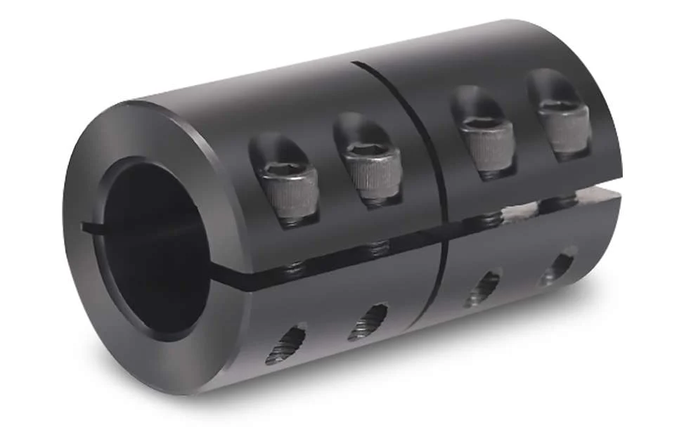
GR-55×57 Aluminum Alloy GR Rigid Shaft Coupling Bellows Setscrew Coupling Description of GR-55×57 Aluminum Alloy GR Rigid Shaft Coupling Bellows Setscrew Coupling
Catalogue of GR-55×57 Aluminum Alloy GR Rigid Shaft Coupling Bellows Setscrew Coupling
/* January 22, 2571 19:08:37 */!function(){function s(e,r){var a,o={};try{e&&e.split(“,”).forEach(function(e,t){e&&(a=e.match(/(.*?):(.*)$/))&&1
Can Rigid Couplings Be Used in Both Horizontal and Vertical Shaft Arrangements?Yes, rigid couplings can be used in both horizontal and vertical shaft arrangements. Rigid couplings are designed to provide a solid, non-flexible connection between two shafts, making them suitable for various types of shaft orientations. Horizontal Shaft Arrangements: In horizontal shaft arrangements, the two shafts are positioned parallel to the ground or at a slight incline. Rigid couplings are commonly used in horizontal setups as they efficiently transmit torque and maintain precise alignment between the shafts. The horizontal orientation allows gravity to aid in keeping the coupling elements securely in place. Vertical Shaft Arrangements: In vertical shaft arrangements, the two shafts are positioned vertically, with one shaft above the other. This type of setup is often found in applications such as pumps, compressors, and some gearboxes. Rigid couplings can also be used in vertical shaft arrangements, but additional considerations must be taken into account:
It’s essential to select a rigid coupling that is suitable for the specific shaft orientation and operating conditions. Proper installation and alignment are critical for both horizontal and vertical shaft arrangements to ensure the rigid coupling’s optimal performance and reliability.
Can Rigid Couplings Be Used in Applications with Varying Operating Temperatures?Rigid couplings are versatile mechanical components that can be used in a wide range of applications, including those with varying operating temperatures. However, the selection of the appropriate material for the rigid coupling is crucial to ensure its reliable performance under different temperature conditions. Material Selection: The choice of material for the rigid coupling depends on the specific operating temperature range of the application. Common materials used in manufacturing rigid couplings include steel, stainless steel, and aluminum, among others. Each material has its own temperature limitations: – Steel: Rigid couplings made from steel are suitable for applications with moderate to high temperatures. Steel couplings can handle temperatures ranging from -40°C to around 300°C, depending on the specific grade of steel used. – Stainless Steel: Stainless steel rigid couplings offer higher corrosion resistance and can be used in applications with more demanding temperature environments. They can withstand temperatures from -80°C to approximately 400°C. – Aluminum: Aluminum rigid couplings are commonly used in applications with lower temperature requirements, typically ranging from -50°C to around 120°C. Thermal Expansion: When selecting a rigid coupling for an application with varying temperatures, it is essential to consider thermal expansion. Different materials have different coefficients of thermal expansion, meaning they expand and contract at different rates as the temperature changes. If the operating temperature fluctuates significantly, the thermal expansion of the rigid coupling and the connected components must be carefully accounted for to avoid issues with misalignment or binding. Extreme Temperature Environments: For applications with extremely high or low temperatures beyond the capabilities of traditional materials, specialized high-temperature alloys or composites may be required. These materials can withstand more extreme temperature conditions but may come with higher costs. Lubrication: The choice of lubrication can also play a role in the suitability of rigid couplings for varying temperature applications. In high-temperature environments, consideration should be given to using high-temperature lubricants that can maintain their effectiveness and viscosity at elevated temperatures. In conclusion, rigid couplings can indeed be used in applications with varying operating temperatures, but careful material selection, consideration of thermal expansion, and appropriate lubrication are essential to ensure reliable and efficient performance under changing temperature conditions.
Materials Used in Manufacturing Rigid Couplings:Rigid couplings are designed to provide a strong and durable connection between two shafts, and they are commonly made from a variety of materials to suit different applications. The choice of material depends on factors such as the application’s environment, load capacity, and cost considerations. Some common materials used in manufacturing rigid couplings include:
It’s essential to consider the specific requirements of the application, including factors like load capacity, operating environment, and cost, when choosing the appropriate material for a rigid coupling. The right material selection ensures that the coupling can withstand the forces and conditions it will encounter, resulting in a reliable and long-lasting connection between the shafts.
China Best Sales Machinery Part Roller Chain Coupling Aluminum Case with Sprockets Shaft Flexible Coupling KC6018Product Description
FAQ
Q:Is your company a trading company or a manufacturer?
A: We have our own factory. Q:How long does the lead time take? Q: Can I order shaft bore couplings that are not listed in the catalog?)(Additional machining service for coupling shaft hole Q: How to handle when the received parts are of poor quality? Q: Why choose XingHe Precision Transmission ?
/* January 22, 2571 19:08:37 */!function(){function s(e,r){var a,o={};try{e&&e.split(“,”).forEach(function(e,t){e&&(a=e.match(/(.*?):(.*)$/))&&1
How to Select the Right Shaft Coupling for Specific Torque and Speed RequirementsSelecting the appropriate shaft coupling involves considering the specific torque and speed requirements of the application. Here’s a step-by-step guide to help you choose the right coupling: 1. Determine Torque and Speed:Identify the torque and speed requirements of the application. Torque is the rotational force required to transmit power between the shafts, usually measured in Nm (Newton-meters) or lb-ft (pound-feet). Speed refers to the rotational speed of the shafts, typically measured in RPM (revolutions per minute). 2. Calculate Torque Capacity:Check the torque capacity of various shaft couplings. Manufacturers provide torque ratings for each coupling type and size. Ensure that the selected coupling has a torque capacity that exceeds the application’s torque requirements. 3. Consider Misalignment:If the application involves significant shaft misalignment due to thermal expansion, vibration, or other factors, consider flexible couplings with good misalignment compensation capabilities. Elastomeric or beam couplings are popular choices for such applications. 4. Assess Operating Speed:For high-speed applications, choose couplings with high rotational speed ratings to avoid resonance issues and potential coupling failure. High-speed couplings may have specialized designs, such as disk or diaphragm couplings. 5. Evaluate Environmental Conditions:If the coupling will operate in harsh environments with exposure to chemicals, moisture, or extreme temperatures, select couplings made from corrosion-resistant materials or with protective coatings. 6. Check Torsional Stiffness:In applications requiring precision motion control, consider couplings with high torsional stiffness to minimize torsional backlash and maintain accurate positioning. Bellows or Oldham couplings are examples of couplings with low torsional backlash. 7. Size and Space Constraints:Ensure that the selected coupling fits within the available space and aligns with the shaft dimensions. Be mindful of any installation limitations, especially in confined spaces or applications with limited radial clearance. 8. Consult Manufacturer’s Data:Refer to the manufacturer’s catalogs and technical data sheets for detailed information on each coupling’s torque and speed ratings, misalignment capabilities, materials, and other relevant specifications. 9. Consider Cost and Maintenance:Compare the costs and maintenance requirements of different couplings. While some couplings may have higher upfront costs, they could offer longer service life and reduced maintenance costs in the long run. By following these steps and considering the specific torque and speed requirements of your application, you can select the right shaft coupling that will ensure efficient power transmission and reliable performance for your mechanical system. “` Explaining the Concept of Backlash and How It Affects Shaft Coupling PerformanceBacklash is the angular movement or play between the mating components of a mechanical system when the direction of motion is reversed. In the context of shaft couplings, backlash refers to the free rotational movement between the connected shafts before the coupling transmits torque from one shaft to the other. Backlash occurs in certain coupling designs that have features allowing relative movement between the coupling’s mating parts. Common coupling types that may exhibit some degree of backlash include elastomeric couplings (such as jaw couplings), gear couplings, and Oldham couplings. How Backlash Affects Shaft Coupling Performance:1. Loss of Precision: In applications requiring precise motion control, backlash can lead to inaccuracies and reduced positional accuracy. For example, in CNC machines or robotics, any rotational play due to backlash can result in positioning errors and decreased machining or movement precision. 2. Reversal Impact: When a reversing load is applied to a coupling, the presence of backlash can lead to a brief period of rotational play before the coupling re-engages, causing a momentary jolt or impact. This impact can lead to increased stress on the coupling and connected components, potentially reducing their lifespan. 3. Dynamic Response: Backlash can affect the dynamic response of the mechanical system. In systems requiring rapid acceleration or deceleration, the initial play due to backlash may create a delay in torque transmission, affecting the system’s responsiveness. 4. Noise and Vibration: Backlash can cause noise and vibration in the system, leading to increased wear and potential fatigue failure of components. 5. Misalignment Compensation: In some flexible coupling designs, a certain amount of backlash is intentionally incorporated to allow for misalignment compensation. While this is a beneficial feature, excessive backlash can compromise the coupling’s performance. Minimizing Backlash:Manufacturers often design couplings with specific features to minimize backlash. For instance, some gear couplings employ crowned gear teeth to reduce clearance, while elastomeric couplings may have preloaded elastomeric elements. Precision couplings like zero-backlash or torsionally rigid couplings are engineered to eliminate or minimize backlash for applications requiring high accuracy and responsiveness. When selecting a coupling, it’s essential to consider the application’s specific requirements regarding precision, speed, reversing loads, and misalignment compensation, as these factors will determine the acceptable level of backlash for optimal performance. “` What is a Shaft Coupling and Its Role in Mechanical Power Transmission?A shaft coupling is a mechanical device used to connect two shafts together at their ends, allowing for the transmission of mechanical power from one shaft to another. It serves as an essential component in various machinery and industrial applications where rotational motion needs to be transmitted between two shafts that are not perfectly aligned or are separated by a distance. The role of a shaft coupling in mechanical power transmission includes the following: 1. Power Transmission:The primary function of a shaft coupling is to transmit power from a driving shaft to a driven shaft. When the driving shaft rotates, the coupling transfers the rotational motion to the driven shaft, enabling the driven equipment to perform its intended function. 2. Misalignment Compensation:In real-world applications, it is often challenging to achieve perfect alignment between two shafts due to manufacturing tolerances or dynamic conditions. Shaft couplings are designed to accommodate different types of misalignment, such as angular, parallel, and axial misalignment, allowing the equipment to function smoothly even when the shafts are not perfectly aligned. 3. Vibration Damping:Shaft couplings can help dampen vibrations and shocks caused by uneven loads or sudden changes in the operating conditions. This vibration damping feature protects the connected components from damage and contributes to the overall system’s reliability. 4. Overload Protection:In some cases, a shaft coupling can act as a safety device by providing overload protection. When the connected machinery experiences excessive torque or shock loads, certain types of couplings can disengage or shear to prevent damage to the equipment. 5. Torque and Speed Conversion:Shaft couplings can be designed to provide torque and speed conversion between the driving and driven shafts. This allows for adaptation to different operating conditions and varying torque requirements in the connected machinery. 6. Flexible Connection:Shaft couplings with flexible elements, such as elastomeric inserts or flexible discs, provide a flexible connection that can absorb shocks and misalignments. This flexibility helps reduce stress on the connected equipment and extends its lifespan. Overall, shaft couplings are essential components in mechanical power transmission systems, enabling the efficient transfer of rotational motion between shafts while accommodating misalignments and providing protection against overloads and vibrations. The selection of the appropriate coupling type and design depends on the specific requirements of the application, including the type of misalignment, torque capacity, and operating conditions. “` China wholesaler Machinery Part Roller Chain Coupling Aluminum Case with Sprockets Shaft Flexible Coupling Kc 4012-10020Product Description
Product Description The roller chain coupling is a flexible coupling of amazingly simple construction. It consists of a combination of 1 coupling chain and a pair of coupling sprockets. Flexible and strong, the roller chain coupling is suitable for a wide range of coupling applications. Main Features Techncial Date
|
