Product Description
Product Description
|
Product name |
Chain coupling |
|||
|
Material |
Carbon steel material |
|||
|
Structure |
Roller chain+sprocket+cover |
|||
|
Size |
KC3012, KC4012, KC4014, KC4016, KC5014, KC5016, KC5018, KC6018, KC6571, KC6571, KC8018, KC8571, KC8571, KC1571, KC12018, KC12571, KC16018, KC16571, KC20018, KC20571, KC24026 |
|||
|
Other type |
Flexible coupling |
|||
|
Application |
Shaft transmission |
|||
|
Feature |
High performance, light weight, convenient assembly |
|||
Packaging & Shipping
Company Profile
ZheJiang Haorongshengye Electrical Equipment Co., Ltd.
1. Was founded in 2008
2. Our Principle:
“Credibility Supremacy, and Customer First”
3. Our Promise:
“High quality products, and Excellent Service”
4. Our Value:
“Being Honesty, Doing the Best, and Long-lasting Development”
5. Our Aim:
“Develop to be a leader in the power transmission parts industry in the world”
|
6.Our services: |
1).Competitive price |
|||
|
2).High quality products |
||||
|
3).OEM service or can customized according to your drawings |
||||
|
4).Reply your inquiry in 24 hours |
||||
|
5).Professional technical team 24 hours online service |
||||
|
6).Provide sample service |
||||
Main products
Machines
Exbihition
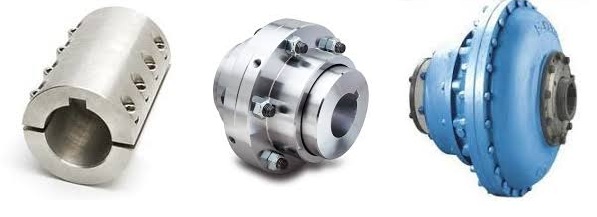
Can Shaft Couplings Compensate for Angular, Parallel, and Axial Misalignments?
Yes, shaft couplings are designed to compensate for different types of misalignments between rotating shafts in mechanical power transmission systems. They can handle the following types of misalignments:
- Angular Misalignment: This occurs when the shafts are not parallel and have an angle between them. Flexible couplings, such as elastomeric, beam, or Oldham couplings, can accommodate angular misalignments by allowing slight angular movement between the shafts while transmitting torque.
- Parallel Misalignment: This happens when the shafts are not collinear, resulting in axial displacement. Flexible couplings with lateral flexibility, like elastomeric or bellows couplings, can handle parallel misalignment by allowing limited lateral movement between the shafts.
- Radial Misalignment: Radial misalignment occurs when the shafts have lateral displacement but remain parallel. Flexible couplings, such as jaw or grid couplings, can absorb radial misalignment by permitting some lateral deflection while transmitting torque.
It is essential to note that while shaft couplings can compensate for misalignments to some extent, they do have their limits. The magnitude of misalignment they can handle depends on the type and design of the coupling. Exceeding the specified misalignment capabilities of a coupling can lead to premature wear, reduced efficiency, and possible coupling failure.
Therefore, when selecting a shaft coupling for an application, it is crucial to consider the expected misalignment and choose a coupling that can accommodate the anticipated misalignment range. Additionally, maintaining proper alignment through regular maintenance and periodic inspections is essential to ensure the coupling’s optimal performance and extend its service life.
“`
Temperature and Speed Limits for Different Shaft Coupling Types
The temperature and speed limits of shaft couplings vary depending on the materials and design of the coupling. Manufacturers provide specific guidelines and ratings for each coupling type. Below are general temperature and speed limits for some common shaft coupling types:
1. Elastomeric Couplings:
Elastomeric couplings, such as jaw couplings and tire couplings, typically have temperature limits ranging from -40°C to 100°C (-40°F to 212°F). The speed limits for elastomeric couplings are generally up to 5,000 RPM, but some designs may allow higher speeds.
2. Metallic Couplings:
Metallic couplings, like gear couplings and disc couplings, can handle a wider temperature range, typically from -50°C to 200°C (-58°F to 392°F). The speed limits for metallic couplings vary based on the size and design, but they can range from 3,000 RPM to over 10,000 RPM.
3. Grid Couplings:
Grid couplings have temperature limits similar to metallic couplings, ranging from -50°C to 200°C (-58°F to 392°F). The speed limits for grid couplings are typically in the range of 3,000 to 5,000 RPM.
4. Oldham Couplings:
Oldham couplings usually have temperature limits from -30°C to 100°C (-22°F to 212°F) and speed limits ranging from 1,000 to 5,000 RPM.
5. Beam Couplings:
Beam couplings generally have temperature limits from -40°C to 120°C (-40°F to 248°F) and speed limits between 5,000 to 10,000 RPM.
6. Fluid Couplings:
Fluid couplings are suitable for a wide range of temperatures, often from -50°C to 300°C (-58°F to 572°F). The speed limits depend on the size and design of the fluid coupling but can extend to several thousand RPM.
It’s important to note that these are general guidelines, and the actual temperature and speed limits may vary based on the specific coupling manufacturer, material quality, and application requirements. Always refer to the manufacturer’s documentation and technical specifications for accurate and up-to-date temperature and speed limits for a particular shaft coupling model.
“`
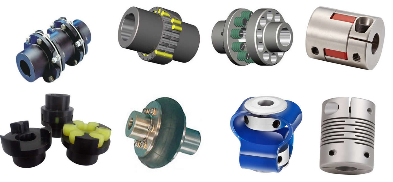
Types of Shaft Couplings and Their Applications in Various Industries
Shaft couplings come in various types, each designed to meet specific application requirements and address different types of misalignment. Here are some common types of shaft couplings and their applications in various industries:
1. Jaw Couplings:
Applications: Jaw couplings are widely used in power transmission applications, including conveyor systems, pumps, compressors, and industrial machinery. They are suitable for moderate torque requirements and provide good misalignment compensation.
2. Gear Couplings:
Applications: Gear couplings are used in heavy-duty industrial applications such as steel mills, paper mills, and mining equipment. They offer high torque capacity and can handle significant misalignments.
3. Disc Couplings:
Applications: Disc couplings are commonly used in precision machinery and automation systems, such as printing presses, machine tools, and robotics. They provide excellent torsional stiffness and are ideal for applications requiring precise positioning.
4. Grid Couplings:
Applications: Grid couplings are used in various industrial applications, including fans, pumps, and compressors. They offer high torque capacity and good shock absorption.
5. Oldham Couplings:
Applications: Oldham couplings are used in applications requiring high misalignment compensation, such as stepper motor drives and motion control systems.
6. Diaphragm Couplings:
Applications: Diaphragm couplings are used in critical applications that demand high torque transmission accuracy, such as aerospace, medical equipment, and semiconductor manufacturing.
7. Elastomeric Couplings:
Applications: Elastomeric couplings, like spider couplings, find applications in general industrial machinery, HVAC systems, and conveyor systems. They provide damping properties and flexibility to accommodate misalignments.
8. Torsionally Rigid Couplings:
Applications: Torsionally rigid couplings are used in applications requiring precise torque transmission, such as precision machining equipment and high-speed spindles.
9. Fluid Couplings:
Applications: Fluid couplings are used in heavy machinery and drivetrains, such as mining equipment, crushers, and marine propulsion systems. They provide smooth acceleration and dampening of shock loads.
10. Magnetic Couplings:
Applications: Magnetic couplings are used in applications where hermetic sealing is required, such as chemical processing, pumps, and mixers. They allow for torque transmission without direct physical contact.
The selection of the appropriate shaft coupling type depends on factors such as torque requirements, speed, misalignment, operating conditions, and the specific needs of the application. Using the right coupling ensures efficient power transmission, protects equipment from misalignment-related issues, and enhances the overall reliability and performance of industrial machinery and systems.
“`

editor by CX 2023-12-14
China high quality Kc Type Spline Shaft Couplings Roller Chain Coupling Rigid Shaft Coupling
Product Description
KC Type Spline Shaft Couplings Roller Chain Coupling Rigid Shaft Coupling
Product Description
Chain coupling: It comprises 2 sprockets, 1 double-row chain, and a yellow shell.
The chain coupling comprises a double-row roller chain and a pair of connecting sprockets. The connection and disassembly functions are completed through the joint of the chain. Our own factory with quality assurance produces the sprocket. Our couplings are characterized by compact structure, sturdiness, durability, safety, and easy installation.
Detailed Photos
Product Parameters
| SIZE | BORE | Pilot | A | d | O | L | I | S | B | C | BOLT | TORQUE ARM(Nm) | SPEED(rpm) | (kg.cm2) | WEIGHT |
| (kg) | |||||||||||||||
| 3012 | 12-16 | 12 | 69 | 25 | 45 | 64.8 | 29.8 | 5.2 | 63 | 10.2 | 6M | 190 | 5000 | 3.7 | 0.4 |
| 4012 | 12-22 | 12 | 77 | 33 | 62 | 79.4 | 36 | 7.4 | 72 | 14.4 | 6M | 249 | 4800 | 5.5 | 0.8 |
| 4014 | 12-28 | 12 | 84 | 43 | 69 | 79.4 | 36 | 7.4 | 75 | 14.4 | 6M | 329 | 4800 | 9.7 | 1.1 |
| 4016 | 14-32 | 14 | 92 | 48 | 77 | 87.4 | 40 | 7.4 | 75 | 14.4 | 6M | 429 | 4800 | 14.4 | 1.4 |
| 5014 | 15-35 | 14 | 101 | 53 | 86 | 99.7 | 45 | 9.7 | 85 | 18.1 | 8M | 620 | 3600 | 28 | 2.2 |
| 5016 | 16-40 | 16 | 111 | 60 | 93 | 99.7 | 45 | 9.7 | 85 | 18.1 | 8M | 791 | 3600 | 37 | 2.7 |
| 5018 | 16-45 | 16 | 122 | 70 | 106 | 99.7 | 45 | 9.7 | 85 | 18.1 | 8M | 979 | 3000 | 56.3 | 3.8 |
| 6018 | 20-56 | 20 | 142 | 85 | 127 | 123.5 | 56 | 11.5 | 105 | 22.8 | 10M | 1810 | 2500 | 137.3 | 6.2 |
| 6571 | 20-60 | 20 | 158 | 98 | 139 | 123.5 | 56 | 11.5 | 105 | 22.8 | 10M | 2210 | 2500 | 210.2 | 7.8 |
| 6571 | 20-71 | 20 | 168 | 110 | 151 | 123.5 | 56 | 11.5 | 117 | 22.8 | 10M | 2610 | 2500 | 295 | 10.4 |
| 8018 | 20-80 | 20 | 190 | 110 | 169 | 141.2 | 63 | 15.2 | 129 | 29.3 | 12M | 3920 | 2000 | 520 | 12.7 |
| 8571 | 20-90 | 20 | 210 | 121 | 185 | 145.2 | 65 | 15.2 | 137 | 29.3 | 12M | 4800 | 2000 | 812.4 | 16 |
| 8571 | 20-100 | 20 | 226 | 140 | 202 | 157.2 | 71 | 15.2 | 137 | 29.3 | 12M | 5640 | 1800 | 1110 | 20.2 |
| 1571 | 25-110 | 25 | 281 | 160 | 233 | 178.8 | 80 | 18.8 | 153 | 35.8 | 12M | 8400 | 1800 | 2440 | 33 |
| 12018 | 35-125 | 35 | 307 | 170 | 256 | 202.7 | 90 | 22.7 | 181 | 45.4 | 12M | 12700 | 1500 | 3940 | 47 |
| 12571 | 35-140 | 35 | 357 | 210 | 304 | 222.7 | 100 | 22.7 | 181 | 45.5 | 12M | 18300 | 1250 | 7810 | 72 |
| 16018 | 63-160 | 35 | 375 | 228 | 340 | 254.1 | 112 | 30.1 | 240 | 58.5 | 16M | 26400 | 1100 | 14530 | 108 |
| 16571 | 80-200 | 70 | 440 | 279 | 405 | 310.1 | 140 | 30.1 | 245 | 58.5 | 16M | 37100 | 1000 | 32220 | 187 |
| 20018 | 82-205 | 75 | 465 | 289 | 425 | 437.5 | 200 | 37.5 | 285 | 71.6 | 20M | 54100 | 800 | 50980 | 286 |
| 20571 | 100-255 | 90 | 545 | 263 | 506 | 477.5 | 220 | 37.5 | 300 | 71.6 | 20M | 77800 | 600 | 111100 | 440 |
| 24571 | 120-310 | 110 | 650 | 448 | 607 | 650 | 302.5 | 45 | 340 | 87.8 | 20M | 137000 | 600 | 310000 | 869 |
| 24026 | 150-360 | 140 | 745 | 526 | 704 | 700 | 327.5 | 45 | 350 | 87.8 | 20M | 186000 | 500 | 598500 | 1260 |
Related Products
Company Profile
FAQ
Q: Can you make the coupling with customization?
A: Yes, we can customize per your request.
Q: Do you provide samples?
A: Yes. The sample is available for testing.
Q: What is your MOQ?
A: It is 10pcs for the beginning of our business.
Q: What’s your lead time?
A: Standard products need 5-30days, a bit longer for customized products.
Q: Do you provide technical support?
A: Yes. Our company has a design and development team, and we can provide technical support if you
need.
Q: How to ship to us?
A: It is available by air, sea, or by train.
Q: How to pay the money?
A: T/T and L/C are preferred, with different currencies, including USD, EUR, RMB, etc.
Q: How can I know if the product is suitable for me?
A: >1ST confirm drawing and specification >2nd test sample >3rd start mass production.
Q: Can I come to your company to visit?
A: Yes, you are welcome to visit us at any time.
Q: How shall we contact you?
A: You can send an inquiry directly, and we will respond within 24 hours.
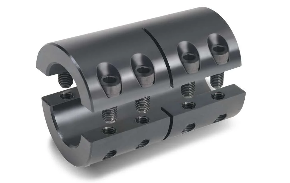
How to Properly Install a Rigid Shaft Coupling for Optimal Performance and Reliability
Proper installation of a rigid shaft coupling is essential to ensure optimal performance and reliability in mechanical systems. Here are the steps to follow for a successful installation:
- Shaft Preparation: Ensure that the shafts to be connected are clean, smooth, and free from any burrs or contaminants that could affect the coupling’s performance.
- Alignment: Align the two shafts accurately to minimize misalignment during installation. The alignment process is critical as any misalignment can lead to premature wear and reduced coupling efficiency.
- Fitment: Choose the appropriate size of the rigid shaft coupling that matches the shaft diameters. Carefully slide the coupling onto one shaft at a time.
- Fastening: For one-piece rigid couplings, ensure that the coupling is fitted snugly onto both shafts. For two-piece couplings, bolt the two halves together securely around the shafts.
- Tightening: Use the recommended torque value and follow the manufacturer’s guidelines to tighten the coupling bolts properly. Over-tightening can cause distortion, while under-tightening can lead to slippage and reduced torque transmission.
- Inspection: After installation, inspect the coupling to ensure that it is centered and aligned correctly. Check for any signs of misalignment or interference during rotation.
- Lubrication: Some rigid couplings may require lubrication at the friction points to reduce wear and friction. Follow the manufacturer’s recommendations for lubrication intervals and types.
- Load Testing: Perform load testing on the system to verify the coupling’s performance and check for any unusual vibrations or noises during operation.
- Regular Maintenance: Include the rigid coupling in your regular maintenance schedule. Periodically check for signs of wear, misalignment, or damage, and replace the coupling if necessary.
By following these installation steps and best practices, you can ensure that the rigid shaft coupling operates optimally, providing reliable torque transmission and contributing to the overall efficiency and longevity of the mechanical system.
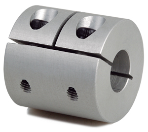
Can rigid shaft couplings reduce vibrations and noise in mechanical systems?
Rigid shaft couplings are primarily designed for accurate torque transmission and shaft alignment. While they are not specifically intended to reduce vibrations and noise, they can indirectly contribute to minimizing vibrations and noise in mechanical systems.
Here’s how rigid shaft couplings can help mitigate vibrations and noise:
- Shaft Alignment: Rigid couplings ensure precise alignment between connected shafts. Proper alignment reduces angular and axial misalignment, which can lead to vibrations and noise. By maintaining alignment, rigid couplings prevent the generation of excessive forces that contribute to vibration.
- Reduced Dynamic Imbalance: Accurate alignment achieved by rigid couplings helps in minimizing dynamic imbalance, which is a common cause of vibrations. When shafts are misaligned, it can lead to uneven distribution of forces and create vibrations in rotating machinery.
- Minimized Wear: Rigid couplings prevent misalignment-induced wear and excessive friction between shafts. This helps in reducing the potential for vibration-producing irregularities that can arise from worn or damaged components.
- Stable Connection: Rigid couplings create a solid and stable connection between shafts. This stability minimizes the likelihood of resonances and vibrations caused by flexible components that might amplify vibrations in the system.
- Uniform Torque Transmission: Rigid couplings facilitate even torque distribution between shafts. Uneven torque transmission can lead to fluctuations and vibration-causing oscillations in the system.
While rigid couplings can provide some indirect benefits in reducing vibrations and noise, they might not be as effective as specialized vibration-damping couplings or other mechanical solutions explicitly designed for vibration and noise reduction. In cases where vibration and noise reduction are critical, engineers might consider incorporating additional measures such as damping materials, flexible couplings, or vibration isolators.
Ultimately, the choice of coupling and vibration reduction strategy depends on the specific requirements of the application. If vibration and noise reduction are primary concerns, it’s advisable to consult with engineering experts and consider coupling designs that prioritize these attributes.
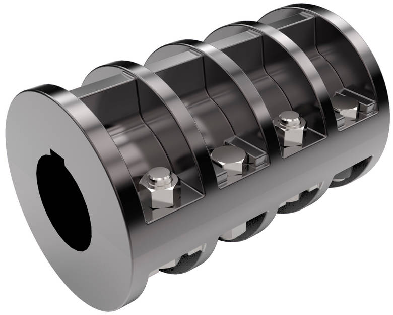
Are There Different Types of Rigid Shaft Couplings Available, and What Are Their Specific Applications?
Yes, there are different types of rigid shaft couplings available, each with its own specific applications. Some common types of rigid shaft couplings include:
- Sleeve Couplings: Sleeve couplings are simple and cost-effective couplings that connect two shafts together using a solid sleeve or tube. They are commonly used in applications with moderate torque requirements and where shaft alignment can be maintained with high precision.
- Clamp or Split Couplings: Clamp or split couplings consist of two halves that are clamped together around the shafts using screws or bolts. They are easy to install and suitable for applications where frequent maintenance or disassembly is required.
- Flanged Couplings: Flanged couplings have flanges on both ends that are bolted together. They are used in applications where shafts need to be rigidly connected and where some degree of axial movement is expected.
- Tapered Shaft Couplings: Tapered shaft couplings have tapered bores that fit tightly onto tapered shafts, creating a friction-based connection. They are often used in applications where precise alignment and torque transmission are essential.
- Keyed Shaft Couplings: Keyed shaft couplings use a key and keyway arrangement to connect the shafts securely. They are commonly used in heavy-duty applications where high torque transmission is required.
The choice of rigid shaft coupling depends on the specific requirements of the application. Factors such as torque transmission, shaft size, alignment precision, ease of installation, and maintenance needs play a crucial role in selecting the appropriate coupling type.
Rigid shaft couplings are widely used in various industries, including manufacturing, power generation, robotics, aerospace, and automotive. They are often employed in applications such as pumps, compressors, conveyors, and high-precision machinery.
It is essential to consider the specific demands of the application and consult with coupling manufacturers or experts to determine the most suitable rigid coupling type for optimal performance and reliability.


editor by CX 2023-11-27