Product Description
Product Description
The maximum opening value is a circular hole or a tapered hole with a keyway.
Main applications:
DWZ disc eddy current brake is mainly used as load in loading dynamometer equipment. it is experimental apparatus which can measure the dynamic mechanical properties, especially in dynamic loading test whose power value is small or tiny, also can be treated as suction power devices of other dynamic devices.
DW series disc eddy current dynamometer is, is that add device for measuring torque and rotational speed on DWZ series disc eddy current brake, it is experimental apparatus which can measure the dynamic mechnical properties, especial in dynamic loading test whose power value is small or tiny.
CW eddy current brake as a load is mainly used to measure the mechanical characteristics of inspection equipment, it and other control instrument (including loading apparatus, torque speed sensor and torque power acquisition instrument etc.) can be composed of eddy current dynamometer can be used for performance testing of the internal combustion engine, motor, gas turbine, automobile and its dynamic mechanical components, compared with other power measuring device, the CW series power measuring device has the advantages of reliability, high stability and practicability.
| Eddy current brake/dynamometer | Rated Power | Rated torque | Rated speed | Maximum rotational speed | Turning inertia | Maximum excitation voltage | Maximum excitation Current | Cooling water pressure | Flow of the cooling water |
| DWZ/DW-0.75 | 0.75 | 5 | 2000-2600 | 16000 | 0.002 | 80 | 3 | 0.1~0.3 | 1 |
| DWZ/DW-3 | 3 | 10 | 2000-2600 | 14000 | 0.003 | 80 | 3 | 0.1~0.3 | 2 |
| DWZ/DW-6 | 6 | 25 | 2000-2600 | 14000 | 0.003 | 80 | 3 | 0.1~0.3 | 3 |
| DWZ/DW-10 | 10 | 50 | 2000-2600 | 13000 | 0.01 | 80 | 3 | 0.1~0.3 | 4.5 |
| DWZ/DW-16 | 16 | 70 | 2000-2600 | 13000 | 0.02 | 80 | 3.5 | 0.1~0.3 | 6.5 |
| DWZ/DW-25 | 25 | 120 | 2000-2600 | 11000 | 0.05 | 80 | 3.5 | 0.1~0.3 | 15 |
| DWZ/DW-40 | 40 | 160 | 2000-2600 | 10000 | 0.1 | 90 | 4 | 0.1~0.3 | 25 |
| DWZ/DW-63 | 63 | 250 | 2000-2600 | 9000 | 0.18 | 90 | 4 | 0.1~0.3 | 45 |
| DWZ/DW-100 | 100 | 400 | 2000-2600 | 8500 | 0.32 | 120 | 4 | 0.1~0.3 | 60 |
| DWZ/DW-160 | 160 | 600 | 2000-2600 | 8000 | 0.52 | 120 | 5 | 0.1~0.3 | 100 |
| DWZ/DW-250 | 250 | 1100 | 2000-2600 | 7000 | 1.8 | 150 | 5 | 0.2~0.4 | 180 |
| DWZ/DW-300 | 300 | 1600 | 2000-2600 | 6000 | 2.7 | 150 | 5 | 0.2~0.4 | 210 |
| DWZ/DW-400 | 400 | 2200 | 2000-2600 | 5000 | 3.6 | 180 | 10 | 0.2~0.4 | 300 |
| DWZ/DW-630 | 630 | 3600 | 2000-2600 | 5000 | 5.3 | 180 | 10 | 0.2~0.4 | 450 |
/* January 22, 2571 19:08:37 */!function(){function s(e,r){var a,o={};try{e&&e.split(“,”).forEach(function(e,t){e&&(a=e.match(/(.*?):(.*)$/))&&1

How to Properly Install a Rigid Shaft Coupling for Optimal Performance and Reliability
Proper installation of a rigid shaft coupling is essential to ensure optimal performance and reliability in mechanical systems. Here are the steps to follow for a successful installation:
- Shaft Preparation: Ensure that the shafts to be connected are clean, smooth, and free from any burrs or contaminants that could affect the coupling’s performance.
- Alignment: Align the two shafts accurately to minimize misalignment during installation. The alignment process is critical as any misalignment can lead to premature wear and reduced coupling efficiency.
- Fitment: Choose the appropriate size of the rigid shaft coupling that matches the shaft diameters. Carefully slide the coupling onto one shaft at a time.
- Fastening: For one-piece rigid couplings, ensure that the coupling is fitted snugly onto both shafts. For two-piece couplings, bolt the two halves together securely around the shafts.
- Tightening: Use the recommended torque value and follow the manufacturer’s guidelines to tighten the coupling bolts properly. Over-tightening can cause distortion, while under-tightening can lead to slippage and reduced torque transmission.
- Inspection: After installation, inspect the coupling to ensure that it is centered and aligned correctly. Check for any signs of misalignment or interference during rotation.
- Lubrication: Some rigid couplings may require lubrication at the friction points to reduce wear and friction. Follow the manufacturer’s recommendations for lubrication intervals and types.
- Load Testing: Perform load testing on the system to verify the coupling’s performance and check for any unusual vibrations or noises during operation.
- Regular Maintenance: Include the rigid coupling in your regular maintenance schedule. Periodically check for signs of wear, misalignment, or damage, and replace the coupling if necessary.
By following these installation steps and best practices, you can ensure that the rigid shaft coupling operates optimally, providing reliable torque transmission and contributing to the overall efficiency and longevity of the mechanical system.

Can rigid shaft couplings reduce vibrations and noise in mechanical systems?
Rigid shaft couplings are primarily designed for accurate torque transmission and shaft alignment. While they are not specifically intended to reduce vibrations and noise, they can indirectly contribute to minimizing vibrations and noise in mechanical systems.
Here’s how rigid shaft couplings can help mitigate vibrations and noise:
- Shaft Alignment: Rigid couplings ensure precise alignment between connected shafts. Proper alignment reduces angular and axial misalignment, which can lead to vibrations and noise. By maintaining alignment, rigid couplings prevent the generation of excessive forces that contribute to vibration.
- Reduced Dynamic Imbalance: Accurate alignment achieved by rigid couplings helps in minimizing dynamic imbalance, which is a common cause of vibrations. When shafts are misaligned, it can lead to uneven distribution of forces and create vibrations in rotating machinery.
- Minimized Wear: Rigid couplings prevent misalignment-induced wear and excessive friction between shafts. This helps in reducing the potential for vibration-producing irregularities that can arise from worn or damaged components.
- Stable Connection: Rigid couplings create a solid and stable connection between shafts. This stability minimizes the likelihood of resonances and vibrations caused by flexible components that might amplify vibrations in the system.
- Uniform Torque Transmission: Rigid couplings facilitate even torque distribution between shafts. Uneven torque transmission can lead to fluctuations and vibration-causing oscillations in the system.
While rigid couplings can provide some indirect benefits in reducing vibrations and noise, they might not be as effective as specialized vibration-damping couplings or other mechanical solutions explicitly designed for vibration and noise reduction. In cases where vibration and noise reduction are critical, engineers might consider incorporating additional measures such as damping materials, flexible couplings, or vibration isolators.
Ultimately, the choice of coupling and vibration reduction strategy depends on the specific requirements of the application. If vibration and noise reduction are primary concerns, it’s advisable to consult with engineering experts and consider coupling designs that prioritize these attributes.

Can Rigid Shaft Couplings Handle Misalignment Between Shafts Effectively?
Rigid shaft couplings are not designed to accommodate misalignment between shafts effectively. Unlike flexible couplings, which can bend or flex to some degree to compensate for misalignment, rigid couplings are inflexible and require precise alignment for proper operation.
When using rigid shaft couplings, it is crucial to ensure that the two shafts being connected are aligned with high accuracy. Misalignment between the shafts can lead to various issues, including:
- Vibrations: Misalignment can cause vibrations and increase stress on the coupling and connected machinery, leading to premature wear and reduced performance.
- Increased Stress: Misalignment results in additional stress on the shafts and coupling, which may lead to fatigue failure over time.
- Reduced Efficiency: Misalignment can result in power loss and reduced overall system efficiency.
- Noise: Misalignment may generate noise during operation, leading to potential discomfort for operators and additional wear on components.
To ensure the effective functioning of rigid shaft couplings, it is crucial to align the shafts accurately during installation. The alignment process typically involves using precision tools and techniques to achieve the desired alignment tolerances.
For applications where misalignment is expected or unavoidable, flexible couplings such as beam couplings or jaw couplings may be more suitable as they can accommodate slight misalignments and reduce the transmission of shock and vibration between shafts.
Overall, rigid shaft couplings are best suited for applications where precise shaft alignment is feasible and necessary for optimal performance. Proper alignment and regular maintenance are essential to maximize the life and efficiency of rigid couplings in mechanical systems.


editor by CX 2024-05-06
China Good quality Stainless Steel Coupling Transmission Machined Parts Gear Roller Chain Couplings Nm Mh Flange Elastic Spider Disc Elastomeric Rigid Jaw Flexible Shaft Coupling
Product Description
Stainless Steel Coupling Transmission Parts Gear High Quality Good Price Gear Roller Chain Couplings Nm Flange Flexible Elastomeric Stainless Steel Coupling
We are the leading top Chinese coupling manufacturer, and are specializing in various high quality coupling.
1. Material: Cast iron, Rubber.
2. OEM and ODM are available
3. High efficient in transmission
4. Finishing: Painted.
5. High quality with competitive price
6. Different models suitable for your different demands
7. Stock for different bore size on both sides available.
8. Application in wide range of environment.
9. Quick and easy mounting and disassembly.
10. Resistant to oil and electrical insulation.
11. Identical clockwise and anticlockwise rotational characteristics.
12. Small dimension, low weight, high transmitted torque.
13. It has good performance on compensating the misalignment.
Fluid couplings:
Features:
Improve the starting capability of electric motor, protect motor against overloading, damp shock, load
fluctuation and torsional vibration, and balance and load distribution in case of multimotor drives.
Applications:
Belt conveyers, csraper conveyers, and conveyers of all kinds Bucket elevators, ball mills, hoisters, crushers,
excavators, mixers, straighteners, cranes, etc.
Flange Flexible Coupling:
Flexible Coupling Model is widely used for its compact designing,easy installation,convenientmaintenance,small size and
light weight.As long as the’relative displacement between shafts is kept within the specified tolerance,the coupling will
operate the best function and a longer working life,thus it is greatly demanded in medium and minorpower transmission
systems drive by moters,such as speed reducers,hoists,compressor,spining &weaving machines and ball mills,permittable
relative displacement:Radial displacement 0.2-0.6mm ; Angel displacemente 0o 30′–1o 30′
Jaw Couplings:
Click here for more types of couplings
Our Services:
1.Design Services
Our design team has experience in cardan shaft relating to product design and development. If you have any needs for your new product or wish to make further improvements, we are here to offer our support.
2.Product Services
raw materials → Cutting → Forging →Rough machining →Shot blasting →Heat treatment →Testing →Fashioning →Cleaning→ Assembly→Packing→Shipping
3.Samples Procedure
We could develop the sample according to your requirement and amend the sample constantly to meet your need.
4.Research & Development
We usually research the new needs of the market and develop the new model when there is new cars in the market.
5.Quality Control
Every step should be special test by Professional Staff according to the standard of ISO9001 and TS16949.
Company Information:
/* March 10, 2571 17:59:20 */!function(){function s(e,r){var a,o={};try{e&&e.split(“,”).forEach(function(e,t){e&&(a=e.match(/(.*?):(.*)$/))&&1

Can Rigid Shaft Couplings Accommodate Different Shaft Sizes and Handle High Torque Loads?
Yes, rigid shaft couplings are designed to accommodate different shaft sizes and are capable of handling high torque loads. One of the key advantages of rigid couplings is their ability to provide a solid and strong connection between two shafts.
Rigid shaft couplings come in various designs, such as one-piece and two-piece configurations. The one-piece couplings have a solid construction with no moving parts and are ideal for applications where precise alignment and torque transmission are essential.
The two-piece rigid couplings consist of two halves that are bolted together around the shafts, creating a tight and secure connection. These couplings allow for easier installation and removal without the need to move the connected shafts. They are commonly used in applications where frequent maintenance is required.
The design of rigid shaft couplings enables them to handle high torque loads efficiently. The solid and rigid construction allows for the direct transfer of torque from one shaft to another, minimizing power loss and ensuring precise torque transmission.
Moreover, rigid couplings can accommodate different shaft sizes by offering various bore diameters and keyway options. This adaptability allows users to connect shafts of different diameters without the need for additional modifications or couplings.
However, it is crucial to select the appropriate size and type of rigid coupling based on the specific application’s torque requirements and shaft sizes. Properly sized rigid couplings will ensure reliable and efficient power transmission while preventing issues such as misalignment, vibration, and premature wear.

What design considerations are crucial when selecting a rigid shaft coupling for a specific application?
Selecting the right rigid shaft coupling for a specific application involves careful consideration of several design factors to ensure optimal performance and reliability. Here are crucial design considerations to keep in mind:
- Torque Transmission: Determine the maximum torque that the coupling needs to transmit. The coupling’s torque rating should match or exceed the application’s requirements to prevent overloading.
- Shaft Size and Type: Choose a coupling that accommodates the shaft sizes and types of the connected equipment. The coupling’s bore sizes should match the shaft diameters for a secure fit.
- Alignment Capability: Consider the alignment accuracy needed for your application. Rigid couplings offer excellent alignment, but some applications might require higher precision than others.
- Space Constraints: Evaluate the available space around the coupling area. Some couplings might have a compact design suitable for tight spaces, while others might require more clearance.
- Environmental Conditions: Assess the operating environment for factors such as temperature, humidity, and presence of corrosive substances. Choose a coupling with appropriate materials and coatings for durability in the given conditions.
- Shaft Misalignment: Determine the potential misalignments the coupling will need to accommodate. While rigid couplings have limited flexibility, they can handle small misalignments. Consider whether angular or axial misalignments are more significant in your application.
- Operating Speed: Evaluate the rotational speed of the machinery. Some couplings have speed limits, and exceeding these limits can lead to vibrations and premature wear.
- Dynamic Loads: Consider any dynamic loads, shocks, or impacts that the coupling might experience during operation. Choose a coupling that can handle these loads without failure.
- Torsional Rigidity: High torsional rigidity ensures efficient torque transmission and minimizes torsional vibrations. Evaluate whether the coupling’s stiffness aligns with your application’s requirements.
- Attachment Method: Determine how the coupling will be attached to the shafts. Different couplings use set screws, clamps, keyways, or other attachment methods. Select a method that suits your application’s needs.
- Cost Considerations: Balance the desired features with your budget. While more advanced couplings might offer additional benefits, they could also be more expensive.
It’s important to collaborate with coupling manufacturers, engineers, or experts to ensure the selected coupling aligns with the specific demands of your application. Coupling suppliers can provide valuable guidance based on their product knowledge and experience with various applications.
By carefully evaluating these design considerations, you can select a rigid shaft coupling that delivers reliable performance, reduces maintenance needs, and contributes to the overall efficiency of your machinery.

What is a Rigid Shaft Coupling and How Does It Work in Mechanical Systems?
A rigid shaft coupling is a type of coupling used to connect two shafts together in a mechanical system. As the name suggests, it is designed to provide a rigid and solid connection between the shafts, without any flexibility or misalignment compensation.
The primary function of a rigid shaft coupling is to transmit torque from one shaft to another efficiently and with minimal backlash. It achieves this by directly connecting the two shafts using a rigid mechanical interface.
Rigid shaft couplings typically consist of two halves with flanges that are bolted or clamped together around the shaft ends. The flanges are precision machined to ensure accurate alignment of the shafts. Some common types of rigid shaft couplings include:
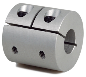
- Sleeve Couplings: These are the simplest type of rigid couplings and consist of a cylindrical sleeve with a bore that fits over the shaft ends. The two shafts are aligned and then secured together using screws or pins.
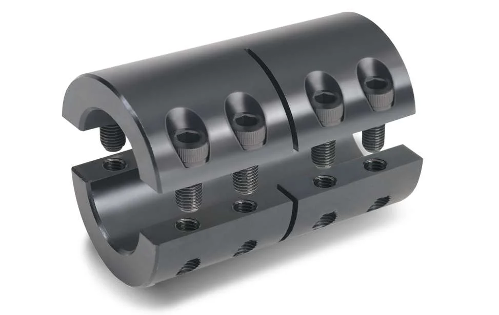
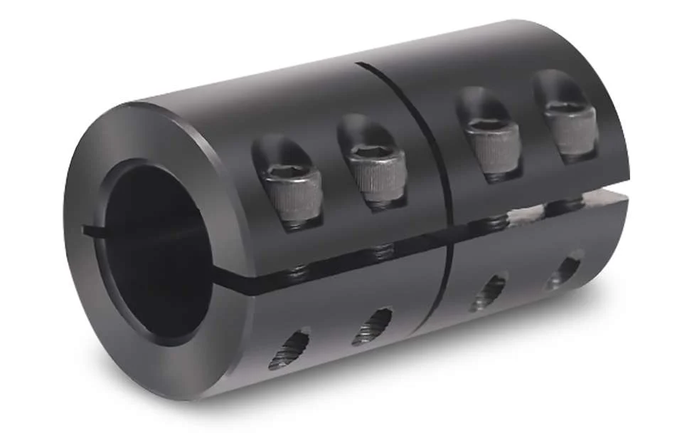
- Clamp or Split Couplings: These couplings have two halves that are split and bolted together around the shafts. The split design allows for easy installation and removal without the need to disassemble other components of the system.
- Flanged Couplings: Flanged couplings have two flanges with precision machined faces that are bolted together, providing a robust connection.
- Tapered Bushing Couplings: These couplings use a tapered bushing to lock the coupling onto the shafts, creating a secure and concentric connection.
Rigid shaft couplings are commonly used in applications where precise alignment is critical, such as in high-speed machinery, precision instruments, and power transmission systems. Since they do not have any flexibility, they are best suited for applications where shaft misalignment is minimal or can be controlled through accurate alignment during installation.
One of the main advantages of rigid shaft couplings is their ability to provide a direct and efficient transfer of torque, making them suitable for high-torque and high-speed applications. Additionally, their simple design and solid connection make them easy to install and maintain.
However, it’s essential to ensure proper alignment during installation to prevent premature wear and stress on the shafts and other components. In cases where misalignment is expected or unavoidable, flexible couplings like beam couplings, bellows couplings, or jaw couplings are more appropriate, as they can compensate for small misalignments and provide some degree of shock absorption.


editor by CX 2024-02-05