Product Description
| Certification | ISO9001:2018;SGS;TS16949 |
| Quality |
CNC machine, CNC Turning, CNC Milling, CNC center machine, auto lathe machine, Wire-cutting Machine CNC punching machines, CNC bending machines CNT stamping machine, CNC/auto lathe machine, Drilling machine, Hydraulic machine, Riveting machine, Tapping machine, welding machine, Film attaching machine, etc. |
| Materials |
Aluminum, Steel, SPCC, SGCC,SECC, SPTE, Stainless steel, Brass, Copper, Bronze, ABS, PC, PO, POM, Nylon, etc. |
| Surface finish |
Anodized, Oxide, Plating, Brushing, Polishing, Blackened, Powder coating, Sandblasting, Laser engraving Zn-plating, Ni-plating, Cr-plating, Tin-plating, copper-plating, the wreath oxygen resin spraying, the heat disposing, hot-dip galvanizing, black oxide coating, painting, powdering, color zinc-plated, blue-black zinc-plated, rust preventive oil, titanium alloy galvanized, silver plating, plastic, electroplating, anodizing, etc |
| Inspection Equipment |
CMM, Projection, Calipers, Micro caliper, Thread Micro caliper, Pin gauge, Caliper gauge, Pass meter, Pass meter, etc. |
| Drawing formation | PDF, CAD/DWG/DXF, IGS/STP etc. |
HangZhou CHINAMFG Industrial Co., Ltd. is a comprehensive factory that specialized in fasteners, CNC parts, stamping parts, machinery parts, and so on. Since the establishment of the company, we have passed ISO9001: 2018, SGS, TS16949.
Our factory covers an area of 5,000 square CHINAMFG and has 58 employees, including 5 R & D personnel and 5 quality inspection personnel.
Major areas of service include automotive, bicycle and motorcycle, industrial automation, agricultural equipment, digital electronics, medical equipment, and so on.
Looking CHINAMFG to your cooperation.
1. We have Specialized QC testers to check the products quality according to customers’ needs.
2. We have IQC to check the dimensions and surface of the incoming material.
3. We have PQC to inspect full-course during the processing.
4. We have FQC to inspect all the plating products from outsides and make the 100% inspection before the shipments.
FAQ:
Q1: Why choose ZheJiang n?
To provide our customers with first-class services in the supply of quality screws minimizing costs.
Q2: How is quality ensured?
All our processes strictly adhere to ISO9001:2018 procedures. We have strict quality control from producing to delivery. Our company had strong technology support, 80% of our colleagues are master or bachelor’s degree. We have cultivated a group of managers who are familiar with product quality , good at modern concept of management.
Q3: Can You Strictly Follow The Tolerance on The Drawing And Meet The High Precision?
Yes, we can, we can provide high precision parts and make the parts as your drawing.
Q4: How should I order and make payment?
By T/T, for samples 100% with the order; for production, 30% paid for deposit by T/T before production arrangement, the balance to be paid before shipment. negotiation accepted.
Q5: What’s your Delivery Time?
Standard parts: 7-20days
Non-standard parts: 15-25days
We will make the delivery as soon as possible with the guarantee quality
Q6:How to Custom-made (OEM/ODM)?
If you have a new product drawing or a sample, please send to us, and we can custom-made the as your required. We will also provide our professional advices of the products to make the design to be more realized & maximize the performance.
Q7:Which mode of transport would be better?
In general, the product are heavy, we advice to make delivery by sea, Also we respect your views of other transportation as well.
/* January 22, 2571 19:08:37 */!function(){function s(e,r){var a,o={};try{e&&e.split(“,”).forEach(function(e,t){e&&(a=e.match(/(.*?):(.*)$/))&&1
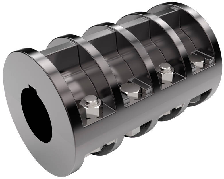
How Does a Rigid Coupling Protect Connected Equipment from Shock Loads and Vibrations?
Rigid couplings play a crucial role in protecting connected equipment from shock loads and vibrations by providing a direct and rigid connection between the shafts. The design and properties of rigid couplings contribute to their ability to mitigate the impact of shock loads and vibrations in the following ways:
– High Stiffness: Rigid couplings are constructed from materials with high stiffness, such as steel or aluminum. This high stiffness allows them to resist deformation and bending under load, ensuring that the coupling remains stable and maintains its shape. As a result, the shock loads and vibrations are not amplified or transferred to the connected equipment.
– Immediate Torque Transmission: Rigid couplings provide immediate torque transmission between the shafts without any backlash or play. When the connected machinery experiences a sudden shock load, the rigid coupling effectively transfers the torque to the other side of the coupling without delay. This rapid and precise torque transfer prevents the shock load from causing misalignment or damaging the equipment.
– Elimination of Damping: Unlike flexible couplings, which can dampen vibrations to some extent, rigid couplings do not have any damping properties. While damping can be beneficial in certain applications, it can also allow vibrations to persist, potentially affecting the performance and reliability of the connected equipment. Rigid couplings do not introduce any additional damping, ensuring that the vibrations are not prolonged.
– Stable Connection: Rigid couplings create a stable and unyielding connection between the shafts, limiting any relative movement. This stability prevents the propagation of vibrations from one shaft to another, reducing the potential for resonance and vibration amplification.
– Minimal Maintenance: Rigid couplings require minimal maintenance due to their simple and durable design. Unlike flexible couplings that may have wear-prone elements, rigid couplings do not have parts that need regular replacement. This reliability and low maintenance contribute to their ability to provide continuous protection against shock loads and vibrations.
In applications where shock loads and vibrations are prevalent, using a rigid coupling can help protect critical machinery and components from damage and premature failure. By providing a rigid and immediate torque transmission, rigid couplings effectively isolate the connected equipment from the harmful effects of shock loads and vibrations, ensuring smooth operation and enhanced reliability.
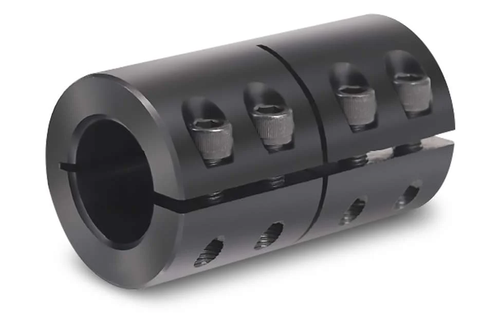
Impact of Rigid Coupling on the Overall Reliability of Connected Equipment
A rigid coupling plays a crucial role in enhancing the overall reliability of connected equipment in mechanical systems. Here’s how it positively impacts reliability:
1. Power Transmission Efficiency: Rigid couplings provide a direct and efficient connection between the shafts of the connected equipment. With no flexible elements, there is minimal power loss, ensuring efficient power transmission from one shaft to another.
2. Elimination of Backlash: Rigid couplings have zero backlash, which is crucial in precision applications. Backlash, which is the play or clearance between connected components, can cause inaccuracies in motion control systems. With a rigid coupling, any movement is directly transferred, maintaining precise positioning.
3. Zero-Maintenance Option: Some rigid couplings are designed to be maintenance-free. They do not require lubrication or periodic adjustments, reducing downtime and ensuring continuous operation.
4. High Torque Transmission: Rigid couplings can handle high torque loads, making them suitable for heavy-duty applications. Their robust construction ensures reliable torque transmission without failure or slippage.
5. Resistant to Misalignment: While rigid couplings offer no flexibility, they are excellent at handling axial misalignment and angular misalignment, provided it falls within their design limits. This ability to tolerate some misalignment enhances reliability and reduces the risk of component damage.
6. Vibration Damping: The stiffness of rigid couplings aids in damping vibrations generated during operation. By minimizing vibrations, the coupling helps protect connected equipment from excessive stress and fatigue failure.
7. Increased System Stiffness: Rigid couplings contribute to the overall stiffness of the mechanical system. This stiffness improves the dynamic response of the system and reduces the likelihood of resonance, leading to more reliable operation.
8. Simple and Compact Design: Rigid couplings have a straightforward and compact design, which reduces the chances of component failure or wear. Their simplicity makes them easy to install and maintain, further enhancing system reliability.
9. Suitable for High-Speed Applications: Rigid couplings are well-suited for high-speed applications due to their ability to maintain accurate shaft alignment and transmit torque efficiently.
10. Compatibility with Various Industries: Rigid couplings find applications in a wide range of industries, including automotive, aerospace, manufacturing, and more. Their versatility and reliability make them a popular choice in demanding industrial environments.
Overall, the use of a properly selected and installed rigid coupling enhances the reliability of connected equipment by providing a robust and efficient connection between shafts. It ensures precise power transmission, reduced maintenance requirements, and improved system performance, leading to increased overall reliability and uptime of the mechanical system.
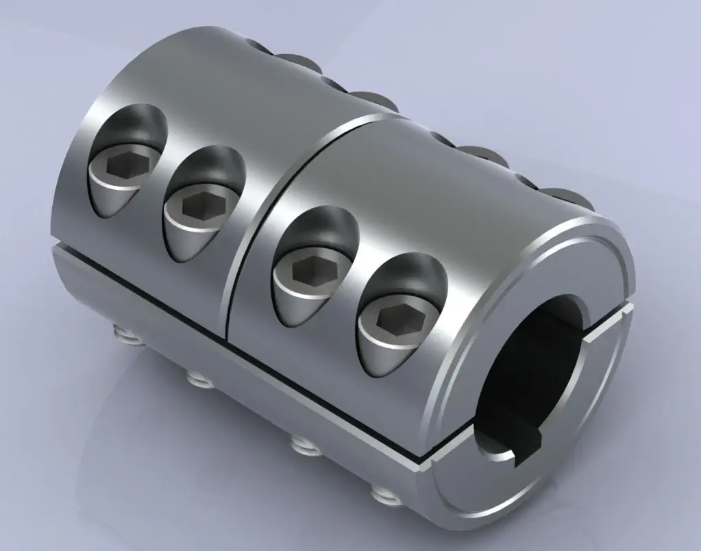
Types of Rigid Coupling Designs:
There are several types of rigid coupling designs available, each designed to meet specific application requirements. Here are some common types of rigid couplings:
- 1. Sleeve Couplings: Sleeve couplings are the simplest type of rigid couplings. They consist of a cylindrical sleeve with a bore in the center that fits over the shaft ends. The coupling is secured in place using setscrews or keyways. Sleeve couplings provide a solid and rigid connection between shafts and are easy to install and remove.
- 2. Clamp or Split Couplings: Clamp couplings, also known as split couplings, are designed with two halves that fit around the shafts and are fastened together with bolts or screws. The split design allows for easy installation and removal without the need to disassemble other components in the system. These couplings are ideal for applications where the shafts cannot be easily moved.
- 3. Flanged Couplings: Flanged couplings have flanges on each end that are bolted together to form a rigid connection. The flanges add stability and strength to the coupling, making them suitable for heavy-duty applications. They are commonly used in industrial machinery and equipment.
- 4. Tapered Couplings: Tapered couplings have a tapered inner diameter that matches the taper of the shaft ends. When the coupling is tightened, it creates a frictional fit between the coupling and the shafts, providing a rigid connection. These couplings are often used in applications where high torque transmission is required.
- 5. Marine or Clampshell Couplings: Marine couplings, also known as clampshell couplings, consist of two halves that encase the shaft ends and are bolted together. These couplings are commonly used in marine applications, such as propeller shafts in boats and ships.
- 6. Diaphragm Couplings: Diaphragm couplings are a type of rigid coupling that provides some flexibility to accommodate misalignment while maintaining a nearly torsionally rigid connection. They consist of thin metal diaphragms that transmit torque while compensating for minor shaft misalignments.
The choice of rigid coupling design depends on factors such as shaft size, torque requirements, ease of installation, and the level of misalignment that needs to be accommodated. It is essential to select the appropriate coupling design based on the specific needs of the application to ensure optimal performance and reliability.


editor by CX 2024-04-02
China supplier Helical Drive Flexible Coupling for Encoder Shaft Coupling Dimensions
Product Description
Helical Drive Flexible Coupling For Encoder Shaft Coupling Dimensions
Product Description
Coupling refers to a device that connects 2 shafts or shafts and rotating parts, rotates together during the transmission of motion and power, and does not disengage under normal conditions. Sometimes it is also usedas a safety device to prevent the connected parts from bearing excessive load, which plays the role of overload protection.
Couplings can be divided into rigid couplings and flexible couplings. Rigid couplings do not have buffering property and the ability to compensate the relative displacement of 2 axes. It is required that the 2 axes be strictly aligned. However, such couplings are simple in structure, low in manufacturing cost, convenient in assembly and disassembly, and maintenance, which can ensure that the 2 axes are relatively neutral, have large transmission torque, and are widely used. Commonly used are flange coupling, sleeve coupling and jacket coupling.
Flexible coupling can also be divided into flexible coupling without elastic element and flexible coupling with elastic element. The former type only has the ability to compensate the relative displacement of 2 axes, but cannot cushion and reduce vibration. Common types include slider coupling, gear coupling, universal coupling and chain coupling; The latter type contains elastic elements. In addition to the ability to compensate the relative displacement
of 2 axes, it also has the functions of buffering and vibration reduction.
Our leading mainly including universal couplings, drum gear couplings, elastic couplings etc.
Main production equipments:
Large lathe, surface grinder, milling machine, spline milling machine, horizontal broaching machine, gear hobbing machine, shaper, slotting machine, bench drilling machine, radial drilling machine, boring machine, band sawing machine, horizontal lathe, end milling machine, crankshaft grinder, CNC milling machine, etc.
Coupling performance
1) Mobility. The movability of the coupling refers to the ability to compensate the relative displacement of 2 rotating components. Factors such as manufacturing and installation errors between connected components, temperature changes during operation and deformation under load all put CHINAMFG requirements for mobility. The movable performance compensates or alleviates the additional load between shafts, bearings, couplings and other components caused by the relative displacement between rotating components.
(2) Buffering. For the occasions where the load is often started or the working load changes, the coupling shall be equipped with elastic elements that play the role of cushioning and vibration reduction to protect the prime mover and the working machine from little or no damage.
(3) Safe, reliable, with sufficient strength and service life.
(4) Simple structure, easy to assemble, disassemble and maintain.
Inspection equipment:
Dynamic balance tester, high-speed intelligent carbon and sulfur analyzer, Blochon optical hardness tester, Leeb hardness tester, magnetic yoke flaw detector etc.
It is widely used in metallurgical steel rolling, wind power, hydropower, mining, engineering machinery, petrochemical, lifting, paper making, rubber, rail transit, shipbuilding and marine engineering and other industries.
How to select the appropriate coupling type
The following items should be considered when selecting the coupling type.
1. The size and nature of the required transmission torque, the requirements for buffering and damping functions, and whether resonance may occur.
2. The relative displacement of the axes of the 2 shafts is caused by manufacturing and assembly errors, shaft load and thermal expansion deformation, and relative movement between components.
3. Permissible overall dimensions and installation methods, and necessary operating space for assembly, adjustment and maintenance. For large couplings, they should be able to be disassembled without axial movement of the shaft.
In addition, the working environment, service life, lubrication, sealing, economy and other conditions should also be considered, and a suitable coupling type should be selected by referring to the characteristics of various couplings.
If you cannot determine the type, you can contact our professional engineer.
FAQ
| Q: What is the payment method? A: We accept TT (Bank Transfer), Western Union, L/C. 1. For total amount under US$500, 100% in advance. 2. For total amount above US$500, 30% in advance, the rest before shipment. |
| Q: What is your MOQ? A: MOQ depends on our client’s needs, besides,we welcome trial order before mass-production. |
| Q: What is the production cycle? A: It varies a lot depending on product dimension,technical requirements and quantity. We always try to meet customers’ requirement by adjusting our workshop schedule. |
| Q: What kind of payment terms do you accept? A: T/T, western union, etc. |
| Q: Is it possible to know how is my product going on without visiting your company? A: We will offer a detailed products schedule and send weekly reports with digital pictures and videos which show the machining progress. |
| Q: If you make poor quality goods,will you refund our fund? A: We make products according to drawings or samples strictly until them reach your 100% satisfaction. And actually we wont take a chance to do poor quality products.We are proud of keeping the spirit of good quality. |
If there’s anything we can help, please feel free to contact with us.
/* January 22, 2571 19:08:37 */!function(){function s(e,r){var a,o={};try{e&&e.split(“,”).forEach(function(e,t){e&&(a=e.match(/(.*?):(.*)$/))&&1
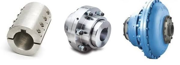
Can Shaft Couplings Compensate for Angular, Parallel, and Axial Misalignments?
Yes, shaft couplings are designed to compensate for different types of misalignments between rotating shafts in mechanical power transmission systems. They can handle the following types of misalignments:
- Angular Misalignment: This occurs when the shafts are not parallel and have an angle between them. Flexible couplings, such as elastomeric, beam, or Oldham couplings, can accommodate angular misalignments by allowing slight angular movement between the shafts while transmitting torque.
- Parallel Misalignment: This happens when the shafts are not collinear, resulting in axial displacement. Flexible couplings with lateral flexibility, like elastomeric or bellows couplings, can handle parallel misalignment by allowing limited lateral movement between the shafts.
- Radial Misalignment: Radial misalignment occurs when the shafts have lateral displacement but remain parallel. Flexible couplings, such as jaw or grid couplings, can absorb radial misalignment by permitting some lateral deflection while transmitting torque.
It is essential to note that while shaft couplings can compensate for misalignments to some extent, they do have their limits. The magnitude of misalignment they can handle depends on the type and design of the coupling. Exceeding the specified misalignment capabilities of a coupling can lead to premature wear, reduced efficiency, and possible coupling failure.
Therefore, when selecting a shaft coupling for an application, it is crucial to consider the expected misalignment and choose a coupling that can accommodate the anticipated misalignment range. Additionally, maintaining proper alignment through regular maintenance and periodic inspections is essential to ensure the coupling’s optimal performance and extend its service life.
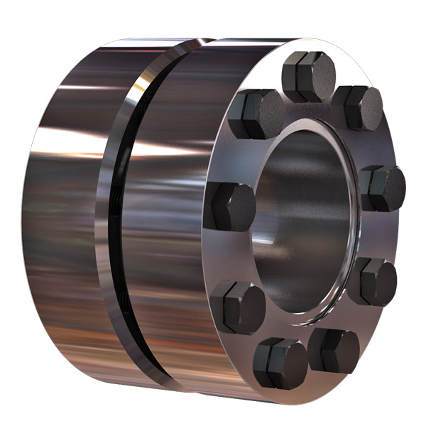
“`
Comparing Shaft Couplings with Other Types of Couplings in Performance
Shaft couplings are essential components in mechanical power transmission systems, and their performance characteristics vary depending on the coupling type. Let’s compare shaft couplings with other common types of couplings:
1. Shaft Couplings:
Shaft couplings come in various designs, including flexible and rigid couplings. They are widely used in a broad range of applications due to their ability to transmit torque and accommodate misalignments between rotating shafts. Flexible shaft couplings, with elastomeric or metallic elements, offer good misalignment compensation and damping characteristics. Rigid couplings, on the other hand, provide precise torque transmission and are ideal for applications where shafts are well-aligned.
2. Gear Couplings:
Gear couplings are robust and designed for heavy-duty applications. They consist of two external gear hubs with internal gear teeth that mesh together. Gear couplings can handle high torque, high-speed, and angular misalignment. They are often used in demanding industries such as steel, mining, and paper manufacturing.
3. Grid Couplings:
Grid couplings feature a flexible grid element between the two halves of the coupling. They provide excellent shock absorption and misalignment compensation. Grid couplings are commonly used in pumps, compressors, and other industrial machinery.
4. Disc Couplings:
Disc couplings utilize flexible metallic discs to transmit torque and compensate for misalignment. They offer high torsional stiffness, making them suitable for applications requiring precise motion control, such as robotics and CNC machines.
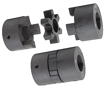
5. Jaw Couplings:
Jaw couplings consist of two hubs with elastomeric spider inserts. They are easy to install, have good misalignment capabilities, and offer electrical isolation between shafts. Jaw couplings are widely used in light to medium-duty applications.
6. Oldham Couplings:
Oldham couplings have three discs—two outer discs with slots and a central disc with a tongue that fits into the slots. They provide excellent angular misalignment compensation while maintaining constant velocity between shafts. Oldham couplings are commonly used in printing machines and conveyors.
7. Beam Couplings:
Beam couplings are made from a single piece of flexible material with spiral cuts. They offer good misalignment compensation and torsional flexibility, making them suitable for precision equipment like encoders and servo motors.
The choice of coupling depends on the specific requirements of the application, including torque, speed, misalignment compensation, environmental conditions, and space limitations. Each coupling type has its strengths and limitations, and selecting the right coupling is crucial to ensure optimal performance and reliability in the mechanical system.
“`
Diagnosing and Fixing Common Issues with Shaft Couplings
Regular inspection and maintenance of shaft couplings are essential to detect and address common issues that may arise during operation. Here are steps to diagnose and fix some common coupling problems:
1. Abnormal Noise or Vibration:
If you notice unusual noise or excessive vibration during equipment operation, it may indicate misalignment, wear, or damage in the coupling. Check for any visible signs of damage, such as cracks or deformations, and inspect the coupling for proper alignment.
Diagnosis:
Use a vibration analysis tool to measure the vibration levels and identify the frequency of the abnormal vibrations. This can help pinpoint the source of the problem.
Fix:
If misalignment is the cause, adjust the coupling to achieve proper alignment between the shafts. Replace any damaged or worn coupling components, such as spiders or elastomeric inserts, as needed.
2. Excessive Heat:
Feeling excessive heat on the coupling during operation can indicate friction, improper lubrication, or overload conditions.
Diagnosis:
Inspect the coupling and surrounding components for signs of rubbing, lack of lubrication, or overloading.
Fix:
Ensure proper lubrication of the coupling, and check for any interference between the coupling and adjacent parts. Address any overloading issues by adjusting the equipment load or using a coupling with a higher torque capacity.
3. Shaft Movement:
If you observe axial or radial movement in the connected shafts, it may indicate wear or improper installation of the coupling.
Diagnosis:
Check the coupling’s set screws, keyways, or other fastening methods to ensure they are secure and not causing the shaft movement.
Fix:
If the coupling is worn or damaged, replace it with a new one. Ensure proper installation and use appropriate fastening methods to secure the coupling to the shafts.
4. Sheared Shear Pin:
In shear pin couplings, a sheared shear pin indicates overloading or shock loads that exceeded the coupling’s torque capacity.
Diagnosis:
Inspect the shear pin for damage or breakage.
Fix:
Replace the sheared shear pin with a new one of the correct specifications. Address any overloading issues or adjust the equipment to prevent future shearing.
5. Coupling Wear:
Regular wear is normal for couplings, but excessive wear may lead to decreased performance and increased misalignment.
Diagnosis:
Inspect the coupling components for signs of wear, such as worn elastomeric elements or damaged teeth.
Fix:
Replace the worn or damaged components with new ones of the appropriate specifications.
Remember, regular maintenance and periodic inspection are key to diagnosing issues early and preventing severe problems. Always follow the manufacturer’s recommendations for maintenance and replacement schedules to ensure the proper functioning and longevity of the shaft coupling.
“`

editor by CX 2024-03-10