Product Description
|
Product Name |
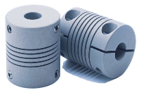
Auto Parts Multi Sizes Spline Coupler Motor Connector Spiral Beam Shaft Couplings |
|
Material |
Aluminum alloy |
|
Surface treatment |
Natural color anode |
|
Customized service |
Support light customization and logo customization |
|
Remarks |
The default engraving brand name and size of the product. If you need not engraving, please contact the customer service for comments |
| Packaging Details | Carton box with anti-static package,carton plus with wooden case. |
| Main Products | Shaft Parts, Timing Belt Pulley, Gears, CNC Machining Parts, Sheet Metal Fabrication |
| Certifications(2) | ISO9001:2015, IPMS |
| Applicable Industries | Building Material Shops, Manufacturing Plant, Food & Beverage Factory, Farms |
| Supply Ability | 100000 Piece/Pieces per Month |
| Dimension | oem provided |
| Surface finish | anodized |
| Lead Time | 25 days |
| Application | Furniture,cabinet |
| Custom | OEM and ODM services are welcome,we can make cutom LOGO and products according to customer’s requests. |
| Quality control Our | Finished product inspection,Warranty available |
| service | Swiss machining;deburring;lathe/turning;5 axis;micromachining |
| Color |
silver,gold,black,red,bulue,and according to the customer requests. |
/* January 22, 2571 19:08:37 */!function(){function s(e,r){var a,o={};try{e&&e.split(“,”).forEach(function(e,t){e&&(a=e.match(/(.*?):(.*)$/))&&1
Exploring the Use of Elastomeric Materials in Flexible Shaft Couplings
Elastomeric materials play a crucial role in the design and function of flexible shaft couplings. These materials, commonly known as elastomers, are rubber-like substances that exhibit high elasticity and flexibility. They are widely used in various types of flexible couplings due to their unique properties and benefits:
1. Damping and Vibration Absorption:
Elastomeric materials have excellent damping characteristics, meaning they can absorb and dissipate vibrations and shocks. This property is particularly useful in applications where vibration control is essential to protect sensitive equipment and improve overall system performance.
2. Misalignment Compensation:
Flexible shaft couplings with elastomeric elements can accommodate different types of misalignments, including angular, parallel, and radial misalignments. The elasticity of the material allows for limited movement between the shafts while still transmitting torque efficiently.
3. Torsional Flexibility:
Elastomers offer torsional flexibility, which allows them to twist and deform under torque loads. This feature helps to minimize torsional stresses and torsional backlash, making them suitable for applications requiring precise motion control.
4. Shock and Impact Resistance:
Due to their high resilience, elastomers can withstand sudden shocks and impacts without permanent deformation. This property makes them ideal for use in machinery subjected to varying loads or rapid changes in torque.
5. No Lubrication Requirement:
Elastomeric couplings are often maintenance-free because the elastomer material does not require additional lubrication. This reduces maintenance costs and simplifies the overall system upkeep.
6. Electric Isolation:
In certain applications, elastomeric materials can provide electrical isolation between the driving and driven components. This can help prevent the transmission of electrical currents or static charges through the coupling.
7. Corrosion Resistance:
Many elastomers used in couplings are resistant to corrosion, making them suitable for use in challenging environments where exposure to chemicals or moisture is a concern.
8. Easy Installation:
Elastomeric couplings are often designed for ease of installation and replacement. Their flexibility allows for simple and quick assembly onto the shafts without the need for special tools or complex procedures.
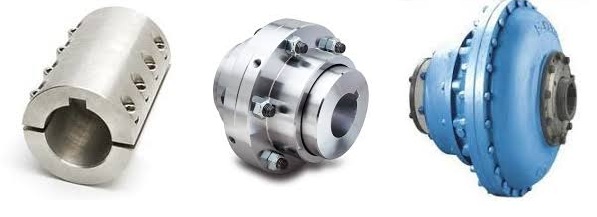
Given these advantages, elastomeric materials are popular choices for various flexible shaft couplings, including jaw couplings, tire couplings, and spider couplings. However, it is essential to select the right elastomer material based on the specific application requirements, such as temperature range, chemical compatibility, and torque capacity.
“`
Explaining the Concept of Backlash and How It Affects Shaft Coupling Performance
Backlash is the angular movement or play between the mating components of a mechanical system when the direction of motion is reversed. In the context of shaft couplings, backlash refers to the free rotational movement between the connected shafts before the coupling transmits torque from one shaft to the other.
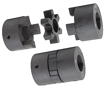
Backlash occurs in certain coupling designs that have features allowing relative movement between the coupling’s mating parts. Common coupling types that may exhibit some degree of backlash include elastomeric couplings (such as jaw couplings), gear couplings, and Oldham couplings.
How Backlash Affects Shaft Coupling Performance:
1. Loss of Precision: In applications requiring precise motion control, backlash can lead to inaccuracies and reduced positional accuracy. For example, in CNC machines or robotics, any rotational play due to backlash can result in positioning errors and decreased machining or movement precision.
2. Reversal Impact: When a reversing load is applied to a coupling, the presence of backlash can lead to a brief period of rotational play before the coupling re-engages, causing a momentary jolt or impact. This impact can lead to increased stress on the coupling and connected components, potentially reducing their lifespan.
3. Dynamic Response: Backlash can affect the dynamic response of the mechanical system. In systems requiring rapid acceleration or deceleration, the initial play due to backlash may create a delay in torque transmission, affecting the system’s responsiveness.
4. Noise and Vibration: Backlash can cause noise and vibration in the system, leading to increased wear and potential fatigue failure of components.
5. Misalignment Compensation: In some flexible coupling designs, a certain amount of backlash is intentionally incorporated to allow for misalignment compensation. While this is a beneficial feature, excessive backlash can compromise the coupling’s performance.
Minimizing Backlash:
Manufacturers often design couplings with specific features to minimize backlash. For instance, some gear couplings employ crowned gear teeth to reduce clearance, while elastomeric couplings may have preloaded elastomeric elements. Precision couplings like zero-backlash or torsionally rigid couplings are engineered to eliminate or minimize backlash for applications requiring high accuracy and responsiveness.
When selecting a coupling, it’s essential to consider the application’s specific requirements regarding precision, speed, reversing loads, and misalignment compensation, as these factors will determine the acceptable level of backlash for optimal performance.
“`
Diagnosing and Fixing Common Issues with Shaft Couplings
Regular inspection and maintenance of shaft couplings are essential to detect and address common issues that may arise during operation. Here are steps to diagnose and fix some common coupling problems:
1. Abnormal Noise or Vibration:
If you notice unusual noise or excessive vibration during equipment operation, it may indicate misalignment, wear, or damage in the coupling. Check for any visible signs of damage, such as cracks or deformations, and inspect the coupling for proper alignment.
Diagnosis:
Use a vibration analysis tool to measure the vibration levels and identify the frequency of the abnormal vibrations. This can help pinpoint the source of the problem.
Fix:
If misalignment is the cause, adjust the coupling to achieve proper alignment between the shafts. Replace any damaged or worn coupling components, such as spiders or elastomeric inserts, as needed.
2. Excessive Heat:
Feeling excessive heat on the coupling during operation can indicate friction, improper lubrication, or overload conditions.
Diagnosis:
Inspect the coupling and surrounding components for signs of rubbing, lack of lubrication, or overloading.
Fix:
Ensure proper lubrication of the coupling, and check for any interference between the coupling and adjacent parts. Address any overloading issues by adjusting the equipment load or using a coupling with a higher torque capacity.
3. Shaft Movement:
If you observe axial or radial movement in the connected shafts, it may indicate wear or improper installation of the coupling.
Diagnosis:
Check the coupling’s set screws, keyways, or other fastening methods to ensure they are secure and not causing the shaft movement.
Fix:
If the coupling is worn or damaged, replace it with a new one. Ensure proper installation and use appropriate fastening methods to secure the coupling to the shafts.
4. Sheared Shear Pin:
In shear pin couplings, a sheared shear pin indicates overloading or shock loads that exceeded the coupling’s torque capacity.
Diagnosis:
Inspect the shear pin for damage or breakage.
Fix:
Replace the sheared shear pin with a new one of the correct specifications. Address any overloading issues or adjust the equipment to prevent future shearing.
5. Coupling Wear:
Regular wear is normal for couplings, but excessive wear may lead to decreased performance and increased misalignment.
Diagnosis:
Inspect the coupling components for signs of wear, such as worn elastomeric elements or damaged teeth.
Fix:
Replace the worn or damaged components with new ones of the appropriate specifications.
Remember, regular maintenance and periodic inspection are key to diagnosing issues early and preventing severe problems. Always follow the manufacturer’s recommendations for maintenance and replacement schedules to ensure the proper functioning and longevity of the shaft coupling.
“`

editor by CX 2024-03-27
China Custom Rigid Shaft Coupling Magnetic Couple Motor Couplings
Product Description
Hot sale: low noise,no leakage, no additional cost for rigid shaft coupling magnetic couple motor couplings
Introduction of rigid shaft coupling magnetic couple motor couplings
Magnetic shaft coupling is a new kind of coupling, which connects motor and machine by permanent magnetic force.
They are consisted of external rotor, internal rotor and isolating covers.
They work in the sealed magnetic drive pumps, which transporting volatile, flammable, explosive and toxic solutions with no leakage.
These magnetic shaft couplings can be used to connect gear pumps , screw pumps, centrifugal pumps, etc. with all types of electric motor or gear box.
Magnetic shaft coupling are widely used in various industries and fields, such as chemical, papermaking, foodstuff, pharmacy, and so on.
Advantages of rigid shaft coupling magnetic couple motor couplings
» Elimination of fluid leakage from the pump shaft.
» Vibrations are not transmitted to the pump.
» No maintenance required for magnetic couplings.
» Using magnetic couplings allows use of standard pumps without expensive mechanical seals.
» No additional cost for purchasing mechanical seal spare parts and maintenance.
Technical drawing of rigid shaft coupling magnetic couple motor couplings
Specification of rigid shaft coupling magnetic couple motor couplings
| Item | Internal Rotor(mm) | External Rotor(mm) | Isolating Covering(mm) | |||||||||||||||||
| A | B | C | D | E | F | G | Shaft Pin | H | I | J | L | N | M | P | Q | R | S | T | U | |
| GME03-3LM00 | Φ35 | – | Φ10 | 26 | – | 18 | – | M6X12 | Φ42 | Φ60 | Φ50 | 46 | 6-M4 | Φ40 | Φ50 | 4-Φ5.4 | Φ38 | Φ60 | 6 | 6 |
| GME03-5MM00 | Φ42 | – | Φ12 | 27 | 4 | 18 | 13.8 | M6X16 | Φ49 | Φ72 | Φ60 | 46 | 4-Φ6.7 | Φ52 | Φ60 | 4-Φ6.7 | Φ44 | Φ74 | 8 | 8 |
| GME03-16LM00 | Φ56 | – | Φ12 | 45 | 4 | 25 | 13.8 | M6X16 | Φ63 | Φ89 | Φ80 | 75 | 6-M5 | Φ70 | Φ75 | 4-Φ6.7 | Φ58 | Φ89 | 8 | 8 |
| GME03-16LM01 | Φ56 | – | Φ12 | 45 | 4 | 25 | 13.8 | M6X16 | Φ63 | Φ89 | Φ80 | 75 | 4-M5 | Φ70 | Φ75 | 4-Φ6.7 | Φ58 | Φ89 | 6 | 10 |
| GME03-16MM00 | Φ56 | – | Φ12 | 45 | 4 | 25 | 13.8 | M6X16 | Φ63 | Φ89 | Φ80 | 75 | 6-M5 | Φ70 | Φ75 | 4-Φ6.7 | Φ58 | Φ89 | 8 | 8 |
| GME03-22LM00 | Φ88 | – | Φ20 | 29 | 6 | 25 | 22.8 | M8X20 | Φ97 | Φ122 | Φ110 | 70 | 8-M6 | Φ98 | Φ108 | 6-Φ6.7 | Φ91 | Φ122 | 8 | 8 |
| GME03-30LM00 | Φ88 | – | Φ20 | 48 | 6 | 30 | 22.8 | M8X20 | Φ97 | Φ122 | Φ110 | 81 | 8-M6 | Φ98 | Φ108 | 6-Φ6.7 | Φ91 | Φ122 | 8 | 8 |
| GME03-40LM00 | Φ101 | – | Φ25 | 49 | 8 | 28 | 28.3 | M10X20 | Φ109 | Φ140 | Φ124 | 83 | 8-M8 | Φ110 | Φ126 | 8-Φ6.7 | Φ103 | Φ140 | 12 | 6 |
| GME03-50LM00 | Φ107 | – | Φ20 | 70 | 6 | 30 | 22.8 | M6X16 | Φ113.4 | Φ145 | Φ135 | 80 | 4-M6 | Φ126 | Φ133 | 12-Φ8.7 | Φ109 | Φ153 | 12 | 15 |
| GME03-65LM00 | Φ101 | – | Φ25 | 77 | 8 | 45 | 28.3 | M10X20 | Φ109 | Φ140 | Φ124 | 111 | 8-M8 | Φ110 | Φ126 | 8-Φ6.7 | Φ103 | Φ140 | 12 | 6 |
| GME03-80LM00 | Φ106 | – | Φ32 | 65 | 10 | 21 | 36.5 | M6X25 | Φ115 | Φ145 | Φ135 | 82 | 4-M6 | Φ127 | Φ135 | 6-Φ8.7 | Φ110 | Φ153 | 13 | 18 |
| GME03-80LM00 | Φ141 | Φ92 | Φ40 | 65 | 12 | 45 | 43.3 | M12X25 | Φ152 | Φ180 | Φ168 | 100 | 8-M8 | Φ154 | Φ164 | 8-Φ6.7 | Φ145 | Φ180 | 12 | 8 |
| GME03-100LM00 | Φ131 | Φ82 | Φ32 | 80 | 10 | 24.5 | 35.3 | M8X35 | Φ139 | Φ170 | Φ160 | 100 | 4-M6 | Φ152 | Φ158 | 8-Φ8.7 | Φ133 | Φ178 | 14 | 21 |
| GME03-110LH00 | Φ141 | Φ92 | Φ40 | 85 | 10 | 50 | 43.3 | M12X25 | Φ152 | Φ184 | Φ168 | 115 | 12-M8 | Φ156 | Φ164 | 12-Φ6.7 | Φ145 | Φ180 | 12 | 3 |
| GME03-110LM00 | Φ141 | Φ92 | Φ35 | 80 | 10 | 55 | 38.3 | M12X25 | Φ152 | Φ180 | Φ168 | 115 | 12-M8 | Φ154 | Φ164 | 12-Φ6.7 | Φ145 | Φ180 | 12 | 3 |
| GME03-140LM00 | Φ141 | Φ92 | Φ40 | 110 | 12 | 80 | 43.3 | M12X25 | Φ152 | Φ190 | Φ170 | 145 | 12-M10 | Φ154 | Φ164 | 12-Φ6.7 | Φ145 | Φ180 | 12 | 3 |
| GME03-180LM00 | Φ141 | Φ92 | Φ40 | 140 | 12 | 95 | 43.3 | M12X25 | Φ152 | Φ190 | Φ170 | 175 | 12-M10 | Φ154 | Φ164 | 12-Φ6.7 | Φ145 | Φ180 | 12 | 3 |
| GME03-220LM00 | Φ141 | Φ92 | Φ48 | 160 | 14 | 110 | 51.8 | M12X25 | Φ152 | Φ190 | Φ170 | 195 | 12-M10 | Φ154 | Φ164 | 12-Φ6.7 | Φ145 | Φ180 | 12 | 3 |
| GME03-300LM00 | Φ162 | – | Φ65 | 100 | 18 | 60 | 69.4 | Φ170 | Φ198 | Φ188 | 123 | 12-M6 | Φ180 | Φ192 | 12-Φ11 | Φ163.5 | Φ218 | 16 | 10 | |
| GME03-400LH00 | Φ195 | – | Φ70 | 127 | 20 | 107 | 79.9 | M12X25 | Φ203 | Φ234 | Φ222 | 152 | 6-M6 | Φ212 | Φ164 | 12-Φ11 | Φ198 | Φ278 | 16 | 22 |
Application of rigid shaft coupling magnetic couple motor couplings
The ability to hermetically separate 2 areas whilst continuing to transmit mechanical power from one to the other makes these couplings ideal for applications where prevention of cross contamination is essential. For instance: hydraulic sectors, dosing systems, compressors, sterilizers, industrial ovens, biotechnology, subsea equipment, pharmaceutical industry, chemical industry, food industry, generators and mixers.
Operation principles of rigid shaft coupling magnetic couple motor couplings
The magnetic coupling works by using the power generated by permanent magnets. No external power supply is needed. These are permanent magnets not electro magnets.
Packing Method of rigid shaft coupling magnetic couple motor couplings
Double strength corrugated Carton and Wood case Sea Packing.
/* January 22, 2571 19:08:37 */!function(){function s(e,r){var a,o={};try{e&&e.split(“,”).forEach(function(e,t){e&&(a=e.match(/(.*?):(.*)$/))&&1
How to Properly Install a Rigid Shaft Coupling for Optimal Performance and Reliability
Proper installation of a rigid shaft coupling is essential to ensure optimal performance and reliability in mechanical systems. Here are the steps to follow for a successful installation:
- Shaft Preparation: Ensure that the shafts to be connected are clean, smooth, and free from any burrs or contaminants that could affect the coupling’s performance.
- Alignment: Align the two shafts accurately to minimize misalignment during installation. The alignment process is critical as any misalignment can lead to premature wear and reduced coupling efficiency.
- Fitment: Choose the appropriate size of the rigid shaft coupling that matches the shaft diameters. Carefully slide the coupling onto one shaft at a time.
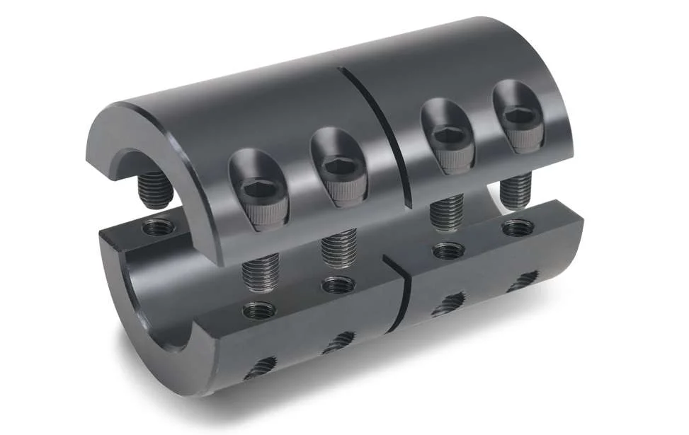
- Fastening: For one-piece rigid couplings, ensure that the coupling is fitted snugly onto both shafts. For two-piece couplings, bolt the two halves together securely around the shafts.
- Tightening: Use the recommended torque value and follow the manufacturer’s guidelines to tighten the coupling bolts properly. Over-tightening can cause distortion, while under-tightening can lead to slippage and reduced torque transmission.
- Inspection: After installation, inspect the coupling to ensure that it is centered and aligned correctly. Check for any signs of misalignment or interference during rotation.
- Lubrication: Some rigid couplings may require lubrication at the friction points to reduce wear and friction. Follow the manufacturer’s recommendations for lubrication intervals and types.
- Load Testing: Perform load testing on the system to verify the coupling’s performance and check for any unusual vibrations or noises during operation.
- Regular Maintenance: Include the rigid coupling in your regular maintenance schedule. Periodically check for signs of wear, misalignment, or damage, and replace the coupling if necessary.
By following these installation steps and best practices, you can ensure that the rigid shaft coupling operates optimally, providing reliable torque transmission and contributing to the overall efficiency and longevity of the mechanical system.

Are there any real-world case studies or success stories of using rigid shaft couplings in various engineering projects?
While specific case studies might not be readily available, there are numerous real-world examples of using rigid shaft couplings in various engineering projects across industries. These projects highlight the versatility and benefits of rigid shaft couplings in different applications:
- Industrial Machinery: Rigid shaft couplings are commonly used in industrial machinery such as conveyor systems, pumps, compressors, and machine tools. They ensure precise torque transmission, alignment, and stability in these critical applications, contributing to reliable and efficient operation.
- Robotics: Robotics often require accurate and repeatable motion control. Rigid couplings provide a rigid connection between robotic joints and actuators, ensuring precise movement and positioning.
- Aerospace: In aerospace applications, where safety and reliability are paramount, rigid shaft couplings play a role in connecting various components, such as engine components and control surfaces, ensuring consistent and reliable performance.
- Medical Equipment: Rigid couplings are used in medical devices such as diagnostic equipment, laboratory instruments, and surgical tools. They contribute to accurate motion control and sample manipulation.
- Automotive: Rigid shaft couplings can be found in automotive systems, including drivetrains and transmission systems. They ensure efficient torque transmission and alignment in components such as steering columns.
- Printing and Packaging: Printing presses and packaging machinery rely on rigid couplings to maintain precise alignment between rollers and components, ensuring consistent print quality and packaging accuracy.
While these examples illustrate the broad range of applications where rigid shaft couplings are used, it’s important to note that the success of each project is influenced by factors beyond just the coupling. Proper installation, maintenance, and integration into the overall system are crucial for achieving optimal results.
When considering the implementation of rigid shaft couplings in a project, engineers should collaborate with coupling manufacturers, suppliers, and experienced professionals to ensure proper selection, installation, and operation. By leveraging the advantages of rigid couplings, engineering projects can benefit from improved efficiency, reliability, and performance.
How Rigid Shaft Couplings Ensure Precise and Torque-Resistant Shaft Connections
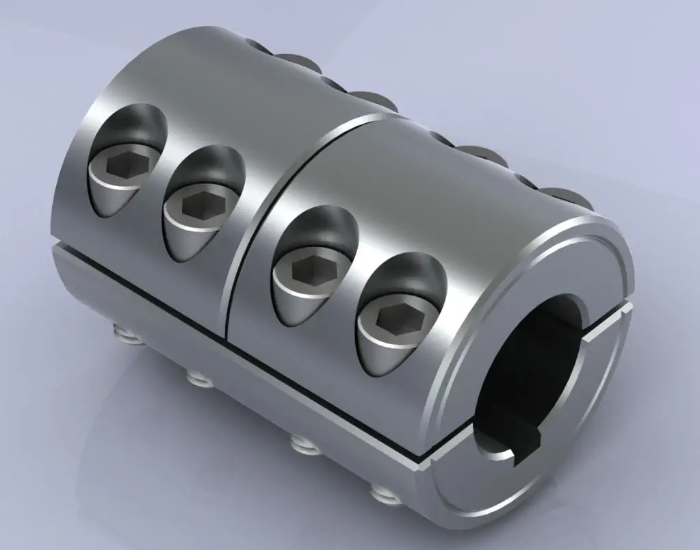
Rigid shaft couplings are designed to provide a solid and inflexible connection between two shafts, ensuring precise alignment and efficient torque transmission. The key features that enable rigid couplings to achieve this include:
- One-Piece Construction: Rigid shaft couplings are typically made from a single piece of material, often metal, without any moving parts or flexible elements. This one-piece construction eliminates the risk of component failure and ensures a stable connection between the shafts.
- Accurate Machining: Rigid couplings undergo precise machining processes to achieve tight tolerances and accurate dimensions. This precision machining ensures that the coupling fits perfectly onto the shafts without any gaps or misalignments.
- High-Quality Materials: Rigid couplings are commonly manufactured from materials such as steel or aluminum, which offer excellent strength and durability. These high-quality materials contribute to the coupling’s ability to handle high torque loads without deformation or wear.
- Keyways and Set Screws: Many rigid shaft couplings feature keyways and set screws for additional security. Keyways are slots on the coupling and shafts that allow the transmission of torque without slippage. Set screws, when tightened against the shafts, create a firm grip, preventing axial movement and enhancing torque resistance.
- Clamping Force: Rigid couplings rely on a clamping force to hold the shafts firmly together. When the coupling is fastened around the shafts, the clamping force creates a strong bond between the coupling and shafts, minimizing any relative movement.
By combining these design elements, rigid shaft couplings ensure that the connected shafts remain in perfect alignment during operation. This precise alignment reduces the risk of misalignment-related issues such as vibrations, premature wear, and decreased efficiency. Additionally, the rigid nature of these couplings allows them to transmit torque without any backlash, providing immediate and accurate responsiveness to changes in torque and rotational direction.
Overall, rigid shaft couplings are an excellent choice for applications that demand precise shaft connections and reliable torque transmission. However, it’s essential to consider factors such as shaft alignment, load capacity, and environmental conditions when selecting the appropriate coupling for a specific application.
“`

editor by CX 2024-03-09
China best Rigid Shaft Coupling Magnetic Couple Motor Couplings
Product Description
Hot sale: low noise,no leakage, no additional cost for rigid shaft coupling magnetic couple motor couplings
Introduction of rigid shaft coupling magnetic couple motor couplings
Magnetic shaft coupling is a new kind of coupling, which connects motor and machine by permanent magnetic force.
They are consisted of external rotor, internal rotor and isolating covers.
They work in the sealed magnetic drive pumps, which transporting volatile, flammable, explosive and toxic solutions with no leakage.
These magnetic shaft couplings can be used to connect gear pumps , screw pumps, centrifugal pumps, etc. with all types of electric motor or gear box.
Magnetic shaft coupling are widely used in various industries and fields, such as chemical, papermaking, foodstuff, pharmacy, and so on.
Advantages of rigid shaft coupling magnetic couple motor couplings
» Elimination of fluid leakage from the pump shaft.
» Vibrations are not transmitted to the pump.
» No maintenance required for magnetic couplings.
» Using magnetic couplings allows use of standard pumps without expensive mechanical seals.
» No additional cost for purchasing mechanical seal spare parts and maintenance.
Technical drawing of rigid shaft coupling magnetic couple motor couplings
Specification of rigid shaft coupling magnetic couple motor couplings
| Item | Internal Rotor(mm) | External Rotor(mm) | Isolating Covering(mm) | |||||||||||||||||
| A | B | C | D | E | F | G | Shaft Pin | H | I | J | L | N | M | P | Q | R | S | T | U | |
| GME03-3LM00 | Φ35 | – | Φ10 | 26 | – | 18 | – | M6X12 | Φ42 | Φ60 | Φ50 | 46 | 6-M4 | Φ40 | Φ50 | 4-Φ5.4 | Φ38 | Φ60 | 6 | 6 |
| GME03-5MM00 | Φ42 | – | Φ12 | 27 | 4 | 18 | 13.8 | M6X16 | Φ49 | Φ72 | Φ60 | 46 | 4-Φ6.7 | Φ52 | Φ60 | 4-Φ6.7 | Φ44 | Φ74 | 8 | 8 |
| GME03-16LM00 | Φ56 | – | Φ12 | 45 | 4 | 25 | 13.8 | M6X16 | Φ63 | Φ89 | Φ80 | 75 | 6-M5 | Φ70 | Φ75 | 4-Φ6.7 | Φ58 | Φ89 | 8 | 8 |
| GME03-16LM01 | Φ56 | – | Φ12 | 45 | 4 | 25 | 13.8 | M6X16 | Φ63 | Φ89 | Φ80 | 75 | 4-M5 | Φ70 | Φ75 | 4-Φ6.7 | Φ58 | Φ89 | 6 | 10 |
| GME03-16MM00 | Φ56 | – | Φ12 | 45 | 4 | 25 | 13.8 | M6X16 | Φ63 | Φ89 | Φ80 | 75 | 6-M5 | Φ70 | Φ75 | 4-Φ6.7 | Φ58 | Φ89 | 8 | 8 |
| GME03-22LM00 | Φ88 | – | Φ20 | 29 | 6 | 25 | 22.8 | M8X20 | Φ97 | Φ122 | Φ110 | 70 | 8-M6 | Φ98 | Φ108 | 6-Φ6.7 | Φ91 | Φ122 | 8 | 8 |
| GME03-30LM00 | Φ88 | – | Φ20 | 48 | 6 | 30 | 22.8 | M8X20 | Φ97 | Φ122 | Φ110 | 81 | 8-M6 | Φ98 | Φ108 | 6-Φ6.7 | Φ91 | Φ122 | 8 | 8 |
| GME03-40LM00 | Φ101 | – | Φ25 | 49 | 8 | 28 | 28.3 | M10X20 | Φ109 | Φ140 | Φ124 | 83 | 8-M8 | Φ110 | Φ126 | 8-Φ6.7 | Φ103 | Φ140 | 12 | 6 |
| GME03-50LM00 | Φ107 | – | Φ20 | 70 | 6 | 30 | 22.8 | M6X16 | Φ113.4 | Φ145 | Φ135 | 80 | 4-M6 | Φ126 | Φ133 | 12-Φ8.7 | Φ109 | Φ153 | 12 | 15 |
| GME03-65LM00 | Φ101 | – | Φ25 | 77 | 8 | 45 | 28.3 | M10X20 | Φ109 | Φ140 | Φ124 | 111 | 8-M8 | Φ110 | Φ126 | 8-Φ6.7 | Φ103 | Φ140 | 12 | 6 |
| GME03-80LM00 | Φ106 | – | Φ32 | 65 | 10 | 21 | 36.5 | M6X25 | Φ115 | Φ145 | Φ135 | 82 | 4-M6 | Φ127 | Φ135 | 6-Φ8.7 | Φ110 | Φ153 | 13 | 18 |
| GME03-80LM00 | Φ141 | Φ92 | Φ40 | 65 | 12 | 45 | 43.3 | M12X25 | Φ152 | Φ180 | Φ168 | 100 | 8-M8 | Φ154 | Φ164 | 8-Φ6.7 | Φ145 | Φ180 | 12 | 8 |
| GME03-100LM00 | Φ131 | Φ82 | Φ32 | 80 | 10 | 24.5 | 35.3 | M8X35 | Φ139 | Φ170 | Φ160 | 100 | 4-M6 | Φ152 | Φ158 | 8-Φ8.7 | Φ133 | Φ178 | 14 | 21 |
| GME03-110LH00 | Φ141 | Φ92 | Φ40 | 85 | 10 | 50 | 43.3 | M12X25 | Φ152 | Φ184 | Φ168 | 115 | 12-M8 | Φ156 | Φ164 | 12-Φ6.7 | Φ145 | Φ180 | 12 | 3 |
| GME03-110LM00 | Φ141 | Φ92 | Φ35 | 80 | 10 | 55 | 38.3 | M12X25 | Φ152 | Φ180 | Φ168 | 115 | 12-M8 | Φ154 | Φ164 | 12-Φ6.7 | Φ145 | Φ180 | 12 | 3 |
| GME03-140LM00 | Φ141 | Φ92 | Φ40 | 110 | 12 | 80 | 43.3 | M12X25 | Φ152 | Φ190 | Φ170 | 145 | 12-M10 | Φ154 | Φ164 | 12-Φ6.7 | Φ145 | Φ180 | 12 | 3 |
| GME03-180LM00 | Φ141 | Φ92 | Φ40 | 140 | 12 | 95 | 43.3 | M12X25 | Φ152 | Φ190 | Φ170 | 175 | 12-M10 | Φ154 | Φ164 | 12-Φ6.7 | Φ145 | Φ180 | 12 | 3 |
| GME03-220LM00 | Φ141 | Φ92 | Φ48 | 160 | 14 | 110 | 51.8 | M12X25 | Φ152 | Φ190 | Φ170 | 195 | 12-M10 | Φ154 | Φ164 | 12-Φ6.7 | Φ145 | Φ180 | 12 | 3 |
| GME03-300LM00 | Φ162 | – | Φ65 | 100 | 18 | 60 | 69.4 | Φ170 | Φ198 | Φ188 | 123 | 12-M6 | Φ180 | Φ192 | 12-Φ11 | Φ163.5 | Φ218 | 16 | 10 | |
| GME03-400LH00 | Φ195 | – | Φ70 | 127 | 20 | 107 | 79.9 | M12X25 | Φ203 | Φ234 | Φ222 | 152 | 6-M6 | Φ212 | Φ164 | 12-Φ11 | Φ198 | Φ278 | 16 | 22 |
Application of rigid shaft coupling magnetic couple motor couplings
The ability to hermetically separate 2 areas whilst continuing to transmit mechanical power from one to the other makes these couplings ideal for applications where prevention of cross contamination is essential. For instance: hydraulic sectors, dosing systems, compressors, sterilizers, industrial ovens, biotechnology, subsea equipment, pharmaceutical industry, chemical industry, food industry, generators and mixers.
Operation principles of rigid shaft coupling magnetic couple motor couplings
The magnetic coupling works by using the power generated by permanent magnets. No external power supply is needed. These are permanent magnets not electro magnets.
Packing Method of rigid shaft coupling magnetic couple motor couplings
Double strength corrugated Carton and Wood case Sea Packing.
Can Rigid Couplings Be Used in Both Horizontal and Vertical Shaft Arrangements?
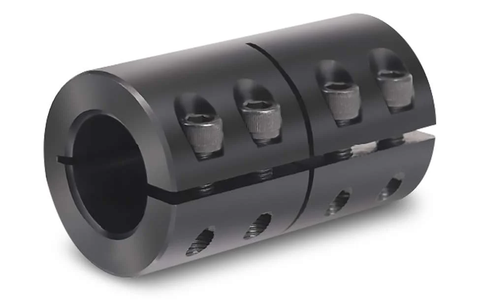
Yes, rigid couplings can be used in both horizontal and vertical shaft arrangements. Rigid couplings are designed to provide a solid, non-flexible connection between two shafts, making them suitable for various types of shaft orientations.
Horizontal Shaft Arrangements: In horizontal shaft arrangements, the two shafts are positioned parallel to the ground or at a slight incline. Rigid couplings are commonly used in horizontal setups as they efficiently transmit torque and maintain precise alignment between the shafts. The horizontal orientation allows gravity to aid in keeping the coupling elements securely in place.
Vertical Shaft Arrangements: In vertical shaft arrangements, the two shafts are positioned vertically, with one shaft above the other. This type of setup is often found in applications such as pumps, compressors, and some gearboxes. Rigid couplings can also be used in vertical shaft arrangements, but additional considerations must be taken into account:
- Keyless Design: To accommodate the vertical orientation, some rigid couplings have a keyless design. Traditional keyed couplings may experience issues with keyway shear due to the force of gravity on the key, especially in overhung load situations.
- Set Screw Tightening: When installing rigid couplings in vertical shaft arrangements, set screws must be tightened securely to prevent any axial movement during operation. Locking compound can also be used to provide additional security.
- Thrust Load Considerations: Vertical shaft arrangements may generate thrust loads due to the weight of the equipment and components. Rigid couplings should be chosen or designed to handle these thrust loads to prevent axial displacement of the shafts.
It’s essential to select a rigid coupling that is suitable for the specific shaft orientation and operating conditions. Proper installation and alignment are critical for both horizontal and vertical shaft arrangements to ensure the rigid coupling’s optimal performance and reliability.

How Does a Rigid Coupling Handle Angular, Parallel, and Axial Misalignment?
Rigid couplings are designed to provide a fixed and rigid connection between two shafts. As such, they do not have any built-in flexibility to accommodate misalignment. Therefore, when using a rigid coupling, it is essential to ensure proper shaft alignment to avoid excessive forces and premature wear on connected equipment.
Angular Misalignment: Angular misalignment occurs when the axes of the two shafts are not collinear and form an angle with each other. Rigid couplings cannot compensate for angular misalignment, and any angular misalignment should be minimized during installation. Precision alignment techniques, such as laser alignment tools, are often used to achieve accurate angular alignment.
Parallel Misalignment: Parallel misalignment, also known as offset misalignment, happens when the axes of the two shafts are parallel but have a lateral displacement from each other. Rigid couplings cannot accommodate parallel misalignment. Therefore, precise alignment is crucial to prevent binding and excessive forces on the shafts and bearings.
Axial Misalignment: Axial misalignment occurs when the two shafts have an axial (longitudinal) displacement from each other. Rigid couplings cannot address axial misalignment. To prevent thrust loads and additional stresses on bearings, it is essential to align the shafts axially during installation.
In summary, rigid couplings are unforgiving to misalignment and require precise alignment during installation. Any misalignment in a rigid coupling can lead to increased wear, premature failure of components, and reduced overall system efficiency. Therefore, it is crucial to use appropriate alignment techniques and tools to ensure optimal performance and longevity of the connected equipment.

Advantages of Using Rigid Couplings in Mechanical Systems:
Rigid couplings offer several advantages when used in mechanical systems. These advantages make them a preferred choice in certain applications where precise alignment and high torque transmission are essential. Here are the key advantages of using rigid couplings:
- 1. High Torque Transmission: Rigid couplings are designed to handle high torque and power transmission without any loss due to flexibility. They provide a direct and solid connection between shafts, allowing for efficient transfer of rotational motion.
- 2. Precise Alignment: Rigid couplings maintain precise alignment between connected shafts. When installed correctly, they ensure that the two shafts are perfectly aligned, which is crucial for applications where accurate positioning and synchronization are required.
- 3. Synchronous Rotation: The rigid connection provided by these couplings enables synchronous rotation of the connected shafts. This is particularly important in applications where components must move in precise coordination with each other.
- 4. Simple Design: Rigid couplings have a straightforward design with minimal moving parts. This simplicity makes them easy to install and maintain, reducing the chances of mechanical failure.
- 5. Cost-Effective: Compared to some other coupling types, rigid couplings are generally more cost-effective. Their simple design and robust construction contribute to their affordability.
- 6. High Strength and Durability: Rigid couplings are typically made from strong and durable materials such as steel, stainless steel, or aluminum. These materials can withstand heavy loads and provide long-lasting performance in demanding applications.
Rigid couplings are commonly used in various industries and applications, including high-precision machinery, robotics, automation systems, precision motion control, and machine tools. They are especially beneficial in scenarios where misalignment needs to be minimized or avoided altogether.
It’s important to note that while rigid couplings offer these advantages, they are not suitable for applications where shaft misalignment or shock absorption is required. In such cases, flexible couplings or other specialized coupling types may be more appropriate.


editor by CX 2023-11-21