Product Description
NL Nylon sleeve internal gear coupling NL8 shaft Couplings Rigid Continous sleeve and double engagement gearing
Product Description
1. Completely interchangeable with the original
2. Suitable for various mechanical engineering and hydraulic fields
3. Nylon and steel material match, maintenance-free
4. Can compensate axial, radial, and angular installation deviation
Product Parameters
| SIZE | MOLD | TOOTH | TORQUE (H.) |
SPEED (r/min) |
MAIN SIZE | ||||||
| SHAFT DIA (d1, d2) |
SHAFT LENGTH (L1,L2) |
L | D | H | D1 D2 | E | |||||
| NL2 | 1.5/1 | 28/42 | 100 | 6000 | 9-22 | 20-45 | CUSTOMIZED | 55 | 40 | 36 | 4 |
| NL3 | 1.5/1 | 34/25 | 160 | 6000 | 9-28 | 20-60 | 66 | 41 | 38-50 | 4 | |
| NL4 | 1.5/2 | 45/32 | 250 | 6000 | 12-38 | 25-80 | 84 | 47 | 50-60 | 4 | |
| NL5 | 2 | 38/36 | 315 | 5000 | 15-42 | 30-110 | 93 | 50 | 60-67 | 4 | |
| NL6 | 2/2.5 | 40/32 | 400 | 5000 | 16-48 | 40-110 | 100 | 51 | 60-70 | 4 | |
| NL7 | 2.5/2 | 36/45 | 630 | 3600 | 16-55 | 45-110 | 115 | 56 | 70-82 | 4 | |
| NL8 | 2.5/3 | 36/45 | 1250 | 3600 | 20-65 | 50-140 | 140 | 70 | 85-95 | 4 | |
| NL9 | 3 | 45/46 | 2000 | 2000 | 20-80 | 60-170 | 175 | 91 | 120 | 6 | |
| NL10 | 4 | 44 | 3150 | 1800 | 38-100 | 70-210 | 220 | 105 | 157 | 8 | |
Related Products
Company Profile
FAQ
Q: Can you make the coupling with customization?
A: Yes, we can customize per your request.
Q: Do you provide samples?
A: Yes. The sample is available for testing.
Q: What is your MOQ?
A: It is 10pcs for the beginning of our business.
Q: What’s your lead time?
A: Standard products need 5-30 days, a bit longer for customized products.
Q: Do you provide technical support?
A: Yes. Our company has a design and development team, and we can provide technical support if you
need.
Q: How to ship to us?
A: It is available by air, sea, or by train.
Q: How to pay the money?
A: T/T and L/C are preferred, with different currencies, including USD, EUR, RMB, etc.
Q: How can I know if the product is suitable for me?
A: >1ST confirm drawing and specification >2nd test sample >3rd start mass production.
Q: Can I come to your company to visit?
A: Yes, you are welcome to visit us at any time.
Q: How shall we contact you?
A: You can send an inquiry directly, and we will respond within 24 hours. /* March 10, 2571 17:59:20 */!function(){function s(e,r){var a,o={};try{e&&e.split(“,”).forEach(function(e,t){e&&(a=e.match(/(.*?):(.*)$/))&&1
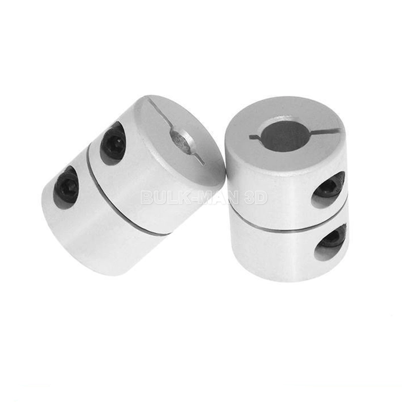
What are the potential drawbacks or limitations of using rigid shaft couplings in certain applications?
Rigid shaft couplings, while offering benefits in certain scenarios, also have limitations that should be considered when selecting them for specific applications:
- Minimal Misalignment Compensation: Rigid couplings have limited ability to compensate for shaft misalignment, making them less suitable for applications with significant misalignment.
- Transmits Vibrations: Rigid couplings do not dampen vibrations, which can lead to increased wear and fatigue in connected components and decrease overall system lifespan.
- Higher Stress Concentration: Due to their rigid nature, these couplings can result in higher stress concentrations at the coupling ends, potentially leading to premature failure.
- Noisy Operation: Rigid couplings can amplify noise generated by connected equipment, contributing to a noisier operating environment.
- Requires Precise Alignment: Proper alignment during installation is crucial to prevent excessive loads on equipment and ensure reliable operation.
- Less Torsional Damping: Rigid couplings lack the torsional damping capabilities of some other coupling types, which may be necessary in systems with varying loads.
- Less Forgiving: Rigid couplings can transmit shocks and impacts directly to connected equipment, which may not be suitable for applications with frequent starts, stops, or heavy loads.
It’s important to carefully assess the specific requirements of an application and consider factors such as misalignment, vibration, torque transmission, and environmental conditions when deciding whether to use a rigid shaft coupling. In cases where the limitations of rigid couplings may pose challenges, other coupling types such as flexible, torsionally soft, or damping couplings could be more appropriate alternatives.
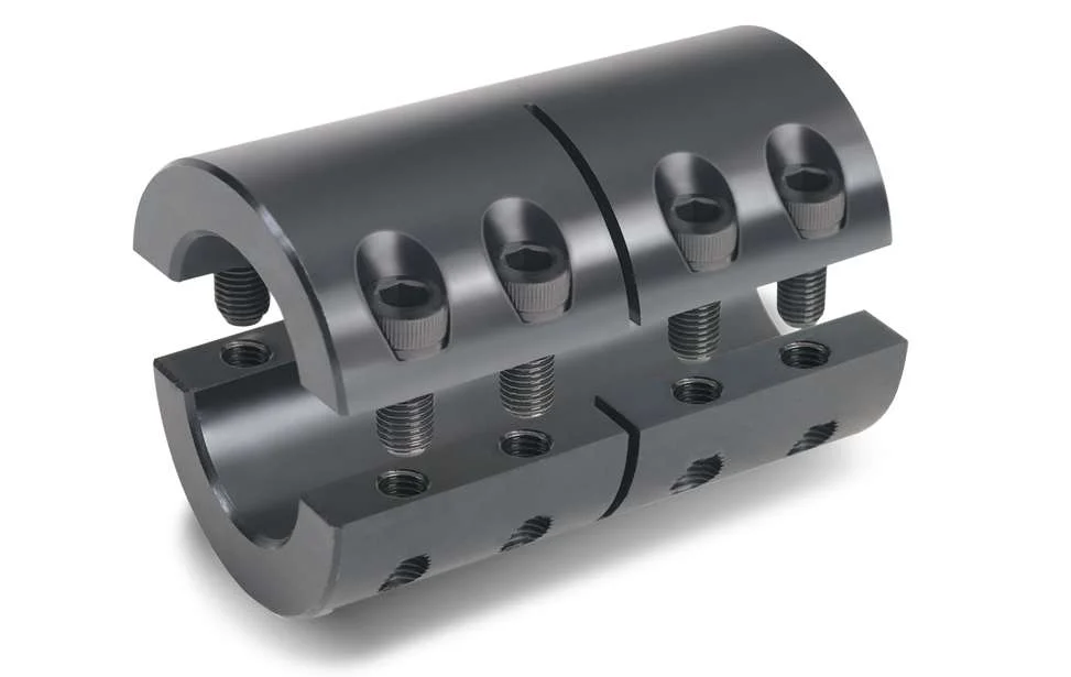
Are there any safety considerations when using rigid shaft couplings in critical applications?
Yes, when using rigid shaft couplings in critical applications, several safety considerations should be taken into account:
- Torsional Stiffness: Rigid couplings have high torsional stiffness, which can lead to increased stresses and potential failures in the connected equipment. Proper analysis of torsional vibrations and stiffness compatibility with the connected components is crucial.
- Shaft Alignment: Inaccurate shaft alignment can lead to additional loads on the coupling and connected machinery. Precision alignment is essential to prevent premature wear, increased stress, and potential breakdowns.
- Overloading: Exceeding the rated torque capacity of the coupling can result in sudden failures and damage to machinery. It’s essential to operate within the coupling’s specified limits to ensure safe operation.
- Maintenance: Regular inspection and maintenance are critical to identify signs of wear, fatigue, or misalignment. Neglecting maintenance can lead to unexpected failures and safety hazards.
- Environmental Factors: Harsh environments, extreme temperatures, and corrosive substances can impact the integrity of rigid couplings. Choosing appropriate materials and protective measures can mitigate these effects.
For critical applications, it’s recommended to work closely with experienced engineers, perform thorough risk assessments, and follow industry standards and best practices to ensure the safe and reliable use of rigid shaft couplings.
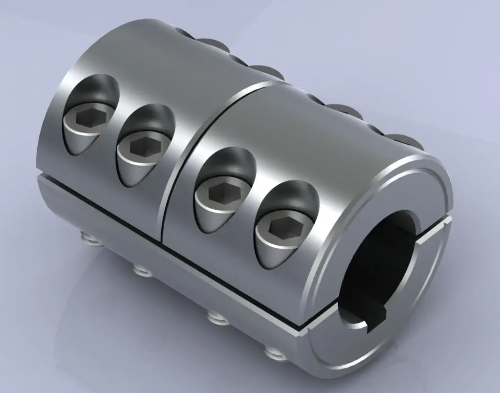
How Rigid Shaft Couplings Ensure Precise and Torque-Resistant Shaft Connections
Rigid shaft couplings are designed to provide a solid and inflexible connection between two shafts, ensuring precise alignment and efficient torque transmission. The key features that enable rigid couplings to achieve this include:
- One-Piece Construction: Rigid shaft couplings are typically made from a single piece of material, often metal, without any moving parts or flexible elements. This one-piece construction eliminates the risk of component failure and ensures a stable connection between the shafts.
- Accurate Machining: Rigid couplings undergo precise machining processes to achieve tight tolerances and accurate dimensions. This precision machining ensures that the coupling fits perfectly onto the shafts without any gaps or misalignments.
- High-Quality Materials: Rigid couplings are commonly manufactured from materials such as steel or aluminum, which offer excellent strength and durability. These high-quality materials contribute to the coupling’s ability to handle high torque loads without deformation or wear.
- Keyways and Set Screws: Many rigid shaft couplings feature keyways and set screws for additional security. Keyways are slots on the coupling and shafts that allow the transmission of torque without slippage. Set screws, when tightened against the shafts, create a firm grip, preventing axial movement and enhancing torque resistance.
- Clamping Force: Rigid couplings rely on a clamping force to hold the shafts firmly together. When the coupling is fastened around the shafts, the clamping force creates a strong bond between the coupling and shafts, minimizing any relative movement.
By combining these design elements, rigid shaft couplings ensure that the connected shafts remain in perfect alignment during operation. This precise alignment reduces the risk of misalignment-related issues such as vibrations, premature wear, and decreased efficiency. Additionally, the rigid nature of these couplings allows them to transmit torque without any backlash, providing immediate and accurate responsiveness to changes in torque and rotational direction.
Overall, rigid shaft couplings are an excellent choice for applications that demand precise shaft connections and reliable torque transmission. However, it’s essential to consider factors such as shaft alignment, load capacity, and environmental conditions when selecting the appropriate coupling for a specific application.
“`

editor by CX 2024-02-24
China OEM 34CrMo4 Scm430 Scm2 4130 Alloy Steel Forgings Gear Rings Shaft Blanks Oil Well Drill Pipe Couplings
Product Description
Product Description
|
Product Name |
FORGING STEEL RING | |||
|
Forging Tolerance |
Construction machinery forging parts forging rings+/-0.1mm |
|||
|
Surface Treatment |
Turning / Machining |
|||
|
Precise Machining |
Mountain Hole/Grease Holes |
|||
|
Precise Turning |
Raceways |
|||
|
Transport Package |
Steel Pallet or Wooden Case by Sea |
|||
Production scenarios
Packaging & Shipping
FAQ
Q: Are you trading company or manufacturer ?
A: We are factory and trading company
Q: How long is your delivery time?
A: Generally it is 5-10 days if the goods are in stock. or it is 15-20 days if the goods are not in stock, it is according to quantity.
Q: Do you provide samples ? is it free or extra ?
A: Yes, we could offer the sample for free charge but do not pay the cost of freight.
Q: What is your terms of payment ?
A: Payment=1000USD, 30% T/T in advance ,balance before shippment.
If you have another question, pls feel free to contact us as below:
/* March 10, 2571 17:59:20 */!function(){function s(e,r){var a,o={};try{e&&e.split(“,”).forEach(function(e,t){e&&(a=e.match(/(.*?):(.*)$/))&&1
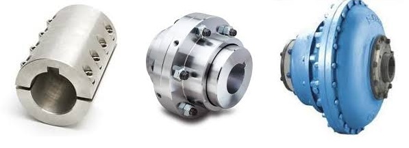
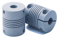
Can Shaft Couplings Compensate for Angular, Parallel, and Axial Misalignments?
Yes, shaft couplings are designed to compensate for different types of misalignments between rotating shafts in mechanical power transmission systems. They can handle the following types of misalignments:
- Angular Misalignment: This occurs when the shafts are not parallel and have an angle between them. Flexible couplings, such as elastomeric, beam, or Oldham couplings, can accommodate angular misalignments by allowing slight angular movement between the shafts while transmitting torque.
- Parallel Misalignment: This happens when the shafts are not collinear, resulting in axial displacement. Flexible couplings with lateral flexibility, like elastomeric or bellows couplings, can handle parallel misalignment by allowing limited lateral movement between the shafts.
- Radial Misalignment: Radial misalignment occurs when the shafts have lateral displacement but remain parallel. Flexible couplings, such as jaw or grid couplings, can absorb radial misalignment by permitting some lateral deflection while transmitting torque.
It is essential to note that while shaft couplings can compensate for misalignments to some extent, they do have their limits. The magnitude of misalignment they can handle depends on the type and design of the coupling. Exceeding the specified misalignment capabilities of a coupling can lead to premature wear, reduced efficiency, and possible coupling failure.
Therefore, when selecting a shaft coupling for an application, it is crucial to consider the expected misalignment and choose a coupling that can accommodate the anticipated misalignment range. Additionally, maintaining proper alignment through regular maintenance and periodic inspections is essential to ensure the coupling’s optimal performance and extend its service life.
“`
Real-World Examples of Shaft Coupling Applications in Different Industries
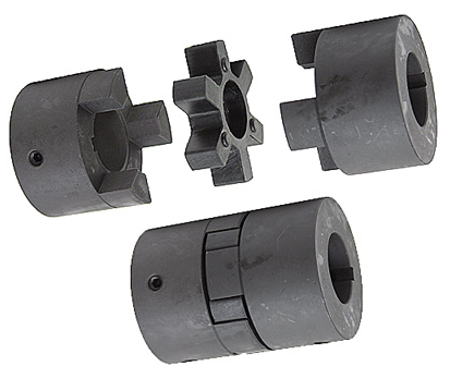
Shaft couplings play a crucial role in various industries by connecting rotating shafts and transmitting torque between them. Here are some real-world examples of shaft coupling applications in different industries:
1. Manufacturing Industry:
In manufacturing plants, shaft couplings are used in various equipment such as conveyor systems, pumps, compressors, and mixers. For example, in a conveyor system, shaft couplings connect the motor shaft to the conveyor belt, allowing efficient material handling and transportation.
2. Oil and Gas Industry:
The oil and gas industry utilizes shaft couplings in applications like drilling rigs, pumps, and generators. In drilling rigs, couplings connect the motor to the drill shaft, enabling the drilling process.
3. Marine Industry:
In the marine industry, shaft couplings are found in propulsion systems, water pumps, and winches. They connect the ship’s engine to the propeller shaft, providing the necessary torque for propulsion.
4. Power Generation:
Power plants use shaft couplings in turbines, generators, and cooling systems. For instance, in a steam turbine, couplings connect the turbine to the electrical generator, allowing the conversion of steam energy into electrical power.
5. Aerospace Industry:
Aerospace applications use shaft couplings in aircraft engines, landing gear systems, and auxiliary power units. Couplings enable power transmission between different components of the aircraft systems.
6. Automotive Industry:
In vehicles, shaft couplings are present in the drivetrain, steering systems, and transmission. For example, in a car’s transmission system, couplings connect the engine to the gearbox, enabling smooth gear changes and power transmission to the wheels.
7. Mining Industry:
The mining industry relies on shaft couplings in heavy-duty machinery such as crushers, conveyor belts, and pumps. Couplings connect motors to various mining equipment, facilitating material extraction and transportation.
8. Agriculture:
Agricultural machinery like tractors and harvesters use shaft couplings to connect the engine to implements such as plows, harvesters, and irrigation pumps.
These examples demonstrate the wide-ranging applications of shaft couplings across industries. In each case, the specific coupling type is chosen based on factors such as torque requirements, misalignment compensation, environmental conditions, and load characteristics to ensure reliable and efficient operation.
“`
Diagnosing and Fixing Common Issues with Shaft Couplings
Regular inspection and maintenance of shaft couplings are essential to detect and address common issues that may arise during operation. Here are steps to diagnose and fix some common coupling problems:
1. Abnormal Noise or Vibration:
If you notice unusual noise or excessive vibration during equipment operation, it may indicate misalignment, wear, or damage in the coupling. Check for any visible signs of damage, such as cracks or deformations, and inspect the coupling for proper alignment.
Diagnosis:
Use a vibration analysis tool to measure the vibration levels and identify the frequency of the abnormal vibrations. This can help pinpoint the source of the problem.
Fix:
If misalignment is the cause, adjust the coupling to achieve proper alignment between the shafts. Replace any damaged or worn coupling components, such as spiders or elastomeric inserts, as needed.
2. Excessive Heat:
Feeling excessive heat on the coupling during operation can indicate friction, improper lubrication, or overload conditions.
Diagnosis:
Inspect the coupling and surrounding components for signs of rubbing, lack of lubrication, or overloading.
Fix:
Ensure proper lubrication of the coupling, and check for any interference between the coupling and adjacent parts. Address any overloading issues by adjusting the equipment load or using a coupling with a higher torque capacity.
3. Shaft Movement:
If you observe axial or radial movement in the connected shafts, it may indicate wear or improper installation of the coupling.
Diagnosis:
Check the coupling’s set screws, keyways, or other fastening methods to ensure they are secure and not causing the shaft movement.
Fix:
If the coupling is worn or damaged, replace it with a new one. Ensure proper installation and use appropriate fastening methods to secure the coupling to the shafts.
4. Sheared Shear Pin:
In shear pin couplings, a sheared shear pin indicates overloading or shock loads that exceeded the coupling’s torque capacity.
Diagnosis:
Inspect the shear pin for damage or breakage.
Fix:
Replace the sheared shear pin with a new one of the correct specifications. Address any overloading issues or adjust the equipment to prevent future shearing.
5. Coupling Wear:
Regular wear is normal for couplings, but excessive wear may lead to decreased performance and increased misalignment.
Diagnosis:
Inspect the coupling components for signs of wear, such as worn elastomeric elements or damaged teeth.
Fix:
Replace the worn or damaged components with new ones of the appropriate specifications.
Remember, regular maintenance and periodic inspection are key to diagnosing issues early and preventing severe problems. Always follow the manufacturer’s recommendations for maintenance and replacement schedules to ensure the proper functioning and longevity of the shaft coupling.
“`

editor by CX 2024-02-14
China OEM CNC Customizable Forged Steel Flexible Jaw Tooth Shaft Gear Couplings
Product Description
|
Material |
20CrMn5,20CrMnTi,40Cr,Powder deposit,45#steel,42CrMo,Stainless steel and so on as per your requests. |
|||
|
Custom |
OEM/ODM |
|||
|
Lead Time |
Sample: 20-30 days after deposit received, Batch goods: 30-45days after samples have been approved. Die opening product:7-15days after samples have been approved.It takes 45-60 days to open the mold. |
|||
|
Processing |
Forging,Machining,Hobbing,Milling,Shaving,Grinding teeth, inserting teeth, shot blasting, Grinding,Heat treatment…… |
|||
|
Heat Treatment |
Intermediate frequency, high frequency, tempering, desalinating, carburizing…… |
|||
|
Main Machines |
CNC gear hobbing machine, CNC gear cutting machine, CNC lathe, CNC gear shaving machine, CNC gear milling machine, CNC gear grinding machine, CNC Grinding Machine…. |
|||
CHINAMFG has been engaged in manufacturing of forgings, castings, heat treatment and CNC machining parts since 1999.
The products materials have passed EN15714-3.1 certification, covering various grades of: low carbon steel, alloy steel, stainless steel, ductile iron, aluminum alloy, copper alloy, titanium alloy.
The main processes are: free forging, die forging, rolling ring, high pressure casting, centrifugal casting, normalizing, quenching and tempering, solution treatment, aging treatment, carbonitriding, turning, milling, drilling, grinding, hobbing, high frequency quenching, galvanizing, chrome plating, anodizing, powder spraying and other processes.
Rings and plates dimensions: Max 3000mm, shafts length: Max 12000mm, single piece weight: Max 16 Tons, at the same time we are good at terminal machining of complex products, dimension accuracy: Min 0.01mm, roughness: Min Ra0.6.
Products can be strictly examined by chemical composition, tensile strength, yield strength, reduction of area, impact at low temperature, intergranular corrosion, hardness, metallographic, NDT, size, static balance etc performance parameter.
Products are widely used in: aerospace, ships, trains, automobiles, engineering vehicles, chemical industry and petroleum refining, wellheads, x-mas tree equipment, mining machinery, food machinery, hydraulic and wind power generation, new energy equipment etc field.
Welcome to send: PDF, IGS, STP and other format drawings, of course we could also make material judgment and size survey according to your samples.
With more than 20 years of manufacturing experience and overseas sales team, we have achieved 100% customer satisfaction. The warranty period of products sold is 365 days. We look CHINAMFG to your consultation and cooperation at any time and common prosperity development.
/* March 10, 2571 17:59:20 */!function(){function s(e,r){var a,o={};try{e&&e.split(“,”).forEach(function(e,t){e&&(a=e.match(/(.*?):(.*)$/))&&1
Is It Possible to Replace a Shaft Coupling Without Professional Assistance?
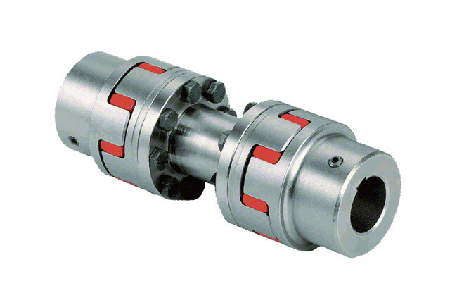
Yes, it is possible to replace a shaft coupling without professional assistance, especially if you have some mechanical knowledge and the necessary tools. However, the ease of replacement can vary depending on the type of coupling and the complexity of the equipment. Here are some general steps to guide you through the process:
1. Safety First:
Before starting any work, ensure that the equipment is turned off and disconnected from the power source. Use appropriate personal protective equipment (PPE) to protect yourself from potential hazards.
2. Assess the Coupling Type:
Different types of couplings may have specific installation and removal methods. Identify the type of coupling you need to replace, and consult the manufacturer’s documentation or online resources for guidance.
3. Gather Tools and Materials:
Collect the necessary tools, such as wrenches, sockets, and a puller (if required), to safely remove the old coupling. Have the new coupling ready for installation, ensuring it matches the specifications of the old one.
4. Disassembly:
If your coupling is a split or clamp-style coupling, you may be able to replace it without fully disassembling the connected equipment. Otherwise, you may need to remove other components to access the coupling.
5. Remove Fasteners:
Loosen and remove any fasteners, such as set screws, that secure the old coupling to the shafts. Take care not to damage the shafts during this process.
6. Extraction:
If the old coupling is tightly fitted on the shafts, you may need to use a coupling puller or other appropriate extraction tools to safely remove it.
7. Clean and Inspect:
After removing the old coupling, clean the shaft ends and inspect them for any signs of damage or wear. Also, check for any misalignment issues that may have contributed to the old coupling’s failure.
8. Install New Coupling:
Follow the manufacturer’s instructions for installing the new coupling. Apply appropriate lubrication and ensure the coupling is correctly aligned with the shafts.
9. Fasten Securely:
Tighten the fasteners to the manufacturer’s recommended torque values to securely attach the new coupling to the shafts.
10. Test Run:
After installation, perform a test run of the equipment to ensure the new coupling operates smoothly and without issues.
While it is possible to replace a shaft coupling without professional assistance, keep in mind that some couplings and equipment may require specialized knowledge and tools for safe and proper replacement. If you are uncertain about the process or encounter any difficulties, it is advisable to seek help from a qualified professional or technician to avoid potential damage to the equipment or injury to yourself.
“`
Explaining the Concept of Backlash and How It Affects Shaft Coupling Performance
Backlash is the angular movement or play between the mating components of a mechanical system when the direction of motion is reversed. In the context of shaft couplings, backlash refers to the free rotational movement between the connected shafts before the coupling transmits torque from one shaft to the other.
Backlash occurs in certain coupling designs that have features allowing relative movement between the coupling’s mating parts. Common coupling types that may exhibit some degree of backlash include elastomeric couplings (such as jaw couplings), gear couplings, and Oldham couplings.
How Backlash Affects Shaft Coupling Performance:
1. Loss of Precision: In applications requiring precise motion control, backlash can lead to inaccuracies and reduced positional accuracy. For example, in CNC machines or robotics, any rotational play due to backlash can result in positioning errors and decreased machining or movement precision.
2. Reversal Impact: When a reversing load is applied to a coupling, the presence of backlash can lead to a brief period of rotational play before the coupling re-engages, causing a momentary jolt or impact. This impact can lead to increased stress on the coupling and connected components, potentially reducing their lifespan.
3. Dynamic Response: Backlash can affect the dynamic response of the mechanical system. In systems requiring rapid acceleration or deceleration, the initial play due to backlash may create a delay in torque transmission, affecting the system’s responsiveness.
4. Noise and Vibration: Backlash can cause noise and vibration in the system, leading to increased wear and potential fatigue failure of components.
5. Misalignment Compensation: In some flexible coupling designs, a certain amount of backlash is intentionally incorporated to allow for misalignment compensation. While this is a beneficial feature, excessive backlash can compromise the coupling’s performance.
Minimizing Backlash:
Manufacturers often design couplings with specific features to minimize backlash. For instance, some gear couplings employ crowned gear teeth to reduce clearance, while elastomeric couplings may have preloaded elastomeric elements. Precision couplings like zero-backlash or torsionally rigid couplings are engineered to eliminate or minimize backlash for applications requiring high accuracy and responsiveness.
When selecting a coupling, it’s essential to consider the application’s specific requirements regarding precision, speed, reversing loads, and misalignment compensation, as these factors will determine the acceptable level of backlash for optimal performance.
“`
Can a Damaged Shaft Coupling Lead to Equipment Failure and Downtime?
Yes, a damaged shaft coupling can lead to equipment failure and downtime in mechanical power transmission systems. Shaft couplings play a critical role in connecting rotating shafts and transmitting power between them. When a coupling becomes damaged or fails to function properly, several negative consequences can arise:
1. Misalignment Issues:
A damaged coupling may no longer be able to compensate for misalignments between the connected shafts. Misalignment can cause excessive vibration, increased wear, and premature failure of bearings and other connected components. Over time, these issues can lead to equipment breakdown and unplanned downtime.
2. Vibration and Shock Loads:
Without the damping properties of a functional coupling, vibrations and shock loads from the driven equipment can transmit directly to the driving shaft and other parts of the system. Excessive vibrations can lead to fatigue failure, cracking, and damage to the equipment, resulting in reduced operational efficiency and increased downtime.
3. Overloading and Torque Transmission:
A damaged coupling may not effectively transmit the required torque between the driving and driven shafts. In applications where the coupling is a safety device (e.g., shear pin couplings), failure to disengage during overloading situations can lead to equipment overload and damage.
4. Increased Wear and Tear:
A damaged coupling can lead to increased wear on other parts of the system. Components such as bearings, seals, and gears may experience higher stress and wear, reducing their lifespan and increasing the likelihood of breakdowns.
5. Reduced System Reliability:
A functional shaft coupling contributes to the overall reliability of the mechanical system. A damaged coupling compromises this reliability, making the system more prone to failures and unplanned maintenance.
6. Downtime and Production Loss:
When a shaft coupling fails, it often results in unscheduled downtime for repairs or replacement. Downtime can be costly for industries that rely on continuous production processes and can lead to production losses and missed delivery deadlines.
7. Safety Hazards:
In certain applications, such as heavy machinery or industrial equipment, a damaged coupling can create safety hazards for workers and surrounding equipment. Sudden failures or uncontrolled movements may pose risks to personnel and property.
Regular inspection, maintenance, and prompt replacement of damaged shaft couplings are essential to prevent equipment failure, minimize downtime, and ensure safe and efficient operation of mechanical systems. It is crucial to address any signs of coupling wear or damage immediately to avoid potential catastrophic failures and costly disruptions to operations.
“`

editor by CX 2024-01-10
China OEM CHINAMFG Gear Coupling for Shaft
Product Description
Product Description
Internal Gear Processing
Internal Gear Ring drawing CHECK, Make Forging Mold, Forging Mold Quality Inspection Check, Machine Processing, Check Size\Hardness\Surface Finish and other technical parameters on drawing.
Inner Gear Package
Spray anti-rust oil on large internal girth Gear, Wrap waterproof cloth around , Prepare package by shaft shape & weight to choose steel frame, steel support or wooden box etc.
OEM Customized Large Inner Gear Ring
We supply OEM SERVICE, customized internal helical gear with big module, more than 1tons big weight, more than 3m length, 42CrMo/35CrMo or your specified required material inner gear ring.
Detailed Photos
Product Parameters
| Module | m | Range: 5~70 |
| Gear Teeth Number | z | OEM/Customized |
| Teeth Height | H | OEM/Customized |
| Teeth Thickness | S | OEM/Customized |
| Tooth pitch | P | OEM/Customized |
| Tooth addendum | Ha | OEM/Customized |
| Tooth dedendum | Hf | OEM/Customized |
| Working height | h’ | OEM/Customized |
| Bottom clearance | C | OEM/Customized |
| Pressure Angle | α | OEM/Customized |
| Helix Angle, | OEM/Customized | |
| Surface hardness | HRC | Range: HRC 50~HRC63(Quenching) |
| Hardness: | HB | Range: HB150~HB280; Hardening Tempering/ Hardened Tooth Surface |
| Surface finish | Range: Ra1.6~Ra3.2 | |
| Tooth surface roughness | Ra | Range: ≥0.4 |
| Gear Accuracy Grade | Grade Range: 5-6-7-8-9 (ISO 1328) | |
| Diameter | d | Range: >1m |
| Weight | Kg | Range: >100kg/ Single Piece |
| Toothed Portion Shape | internal, inner gear ring | |
| Material | Casting 42CrMo/45# steel or Customized | |
| Gear Teeth Milling | √ | |
| Gear Teeth Grinding | √ | |
| Heat Treatment | Quenching /Carburizing | |
| Sand Blasting | Null | |
| Testing | UT\MT | |
| Trademark | TOTEM/OEM | |
| Application | Gearbox, Reducer etc | |
| Transport Package | Export package (steel frame, wooden box, etc.) | |
| Origin | China | |
| HS Code | 8483409000 |
CHINAMFG SERVICE
TOTEM Machinery all the time works to supply GEAR SHAFT, ECCENTRIC SHAFT, HERRINGBONE GEAR, BEVEL GEAR, INTERNAL GEAR and other parts for transmission device & equipment (large industrial reducer & driver). Which mainly use to industrial equipment on fields of port facilities, cement, mining, metallurgical industry etc.
TOTEM Machinery invests and becomes shareholders of several machine processing factories, forging factories, casting factories, relies on these strong reliable and high-quality suppliers’ network, to let customers worry-free purchase.
TOTEM Philosophy: Quality-No.1, Integrity- No.1, Service- No.1
24hrs Salesman on-line, guarantee quick and positive feedback. Experienced and Professional Forwarder Guarantee Log. transportation.
About CHINAMFG
1. Workshop & Processing Strength
2. Testing Facilities
3. Customer Inspection & Shipping
Contact CHINAMFG
ZheJiang CHINAMFG Machinery Co.,Ltd
Facebook: ZheJiang Totem
FAQ
What’s CHINAMFG product processing progress?
Drawing CHECK, Make Forging Mold, Forging Mold Quality Inspection Check, Machine Processing, Check Size\Hardness\Surface Finish and other technical parameters on drawing.
How about TOTEM’s export package?
Spray anti-rust oil on Herringbone Gear Shaft, Wrap waterproof cloth around Gear Shaft for reducer, Prepare package by shaft shape&weight to choose steel frame, steel support or wooden box etc.
Could I customize gear\gear shaft on TOTEM?
We supply customized Gear Shaft,Eccentric Shaft,Herringbone Gear,Internal Gear,Bevel Gear with big module, more than 1tons big weight, more than 3m length, forging or casting 42CrMo/35CrMo or your specified required material.
Why can I choose TOTEM?
TOTEM has 24hrs Salesman on-line, guarantee quick and positive feedback.
TOTEM Machinery invests and becomes shareholders of several machine processing factories, forging factories, casting factories, relies on these strong reliable and high-quality supplier’s network, to let customers worry-free purchase.
Experienced and Professional Forwarder Guarantee Log. transportation.
/* March 10, 2571 17:59:20 */!function(){function s(e,r){var a,o={};try{e&&e.split(“,”).forEach(function(e,t){e&&(a=e.match(/(.*?):(.*)$/))&&1
How to Select the Right Shaft Coupling for Specific Torque and Speed Requirements
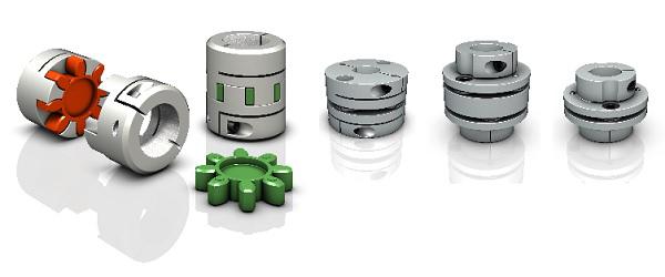
Selecting the appropriate shaft coupling involves considering the specific torque and speed requirements of the application. Here’s a step-by-step guide to help you choose the right coupling:
1. Determine Torque and Speed:
Identify the torque and speed requirements of the application. Torque is the rotational force required to transmit power between the shafts, usually measured in Nm (Newton-meters) or lb-ft (pound-feet). Speed refers to the rotational speed of the shafts, typically measured in RPM (revolutions per minute).
2. Calculate Torque Capacity:
Check the torque capacity of various shaft couplings. Manufacturers provide torque ratings for each coupling type and size. Ensure that the selected coupling has a torque capacity that exceeds the application’s torque requirements.
3. Consider Misalignment:
If the application involves significant shaft misalignment due to thermal expansion, vibration, or other factors, consider flexible couplings with good misalignment compensation capabilities. Elastomeric or beam couplings are popular choices for such applications.
4. Assess Operating Speed:
For high-speed applications, choose couplings with high rotational speed ratings to avoid resonance issues and potential coupling failure. High-speed couplings may have specialized designs, such as disk or diaphragm couplings.
5. Evaluate Environmental Conditions:
If the coupling will operate in harsh environments with exposure to chemicals, moisture, or extreme temperatures, select couplings made from corrosion-resistant materials or with protective coatings.
6. Check Torsional Stiffness:
In applications requiring precision motion control, consider couplings with high torsional stiffness to minimize torsional backlash and maintain accurate positioning. Bellows or Oldham couplings are examples of couplings with low torsional backlash.
7. Size and Space Constraints:
Ensure that the selected coupling fits within the available space and aligns with the shaft dimensions. Be mindful of any installation limitations, especially in confined spaces or applications with limited radial clearance.
8. Consult Manufacturer’s Data:
Refer to the manufacturer’s catalogs and technical data sheets for detailed information on each coupling’s torque and speed ratings, misalignment capabilities, materials, and other relevant specifications.
9. Consider Cost and Maintenance:
Compare the costs and maintenance requirements of different couplings. While some couplings may have higher upfront costs, they could offer longer service life and reduced maintenance costs in the long run.
By following these steps and considering the specific torque and speed requirements of your application, you can select the right shaft coupling that will ensure efficient power transmission and reliable performance for your mechanical system.
“`
How to Identify Signs of Wear or Failure in a Shaft Coupling
Regular inspection and monitoring are essential to identify signs of wear or potential failure in a shaft coupling. Detecting issues early can help prevent costly downtime and equipment damage. Here are common signs to look for:
1. Visible Damage:
Inspect the coupling for visible signs of damage, such as cracks, chips, or deformation. These can indicate mechanical stress or overload.
2. Abnormal Noise or Vibration:
Unusual noise or excessive vibration during operation may indicate misalignment, worn-out components, or a coupling nearing its failure point.
3. Increased Temperature:
If the coupling becomes noticeably hotter during operation than usual, it could be a sign of friction or misalignment issues.
4. Shaft Misalignment:
Check for misalignment between the shafts connected by the coupling. Misalignment can lead to increased stress on the coupling and its components.
5. Excessive Backlash:
If the coupling exhibits too much free play or rotational play before torque transmission, it might indicate wear or fatigue in the coupling’s components.
6. Lubrication Issues:
Inspect the coupling for lubrication leaks or insufficient lubrication, which can lead to increased friction and wear.
7. Elastomeric Element Deterioration:
If the coupling uses elastomeric elements (e.g., rubber or polyurethane), check for signs of deterioration, such as cracking, softening, or deformation.
8. Bolts and Fasteners:
Examine the bolts and fasteners connecting the coupling components. Loose or damaged bolts can lead to misalignment and coupling failure.
9. Age and Service Life:
Consider the age and service life of the coupling. If it has been in use for a long time or exceeds the manufacturer’s recommended service life, it may be more susceptible to wear and failure.
10. Abnormal Performance:
Monitor the overall performance of the connected equipment. Any abnormal behavior, such as reduced power transmission or erratic operation, could be indicative of coupling issues.
If any of these signs are observed, it’s crucial to take immediate action. Depending on the severity of the issue, this may involve replacing worn components, realigning the shafts, or replacing the entire coupling. Regular maintenance and periodic inspections are key to identifying these signs early and ensuring the coupling operates optimally and safely.
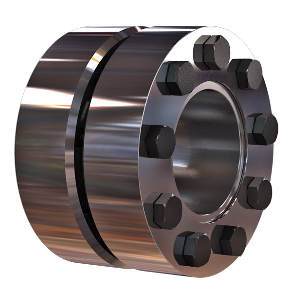
“`
Best Practices for Installing a Shaft Coupling for Optimal Performance
Proper installation of a shaft coupling is crucial for ensuring optimal performance and preventing premature wear or failure. Follow these best practices to install a shaft coupling correctly:
1. Shaft Alignment:
Ensure that both the driving and driven shafts are properly aligned before installing the coupling. Misalignment can lead to increased stress on the coupling and other connected components, reducing efficiency and causing premature wear. Use alignment tools, such as dial indicators or laser alignment systems, to achieve accurate shaft alignment.
2. Cleanliness:
Before installation, clean the shaft ends and the coupling bore thoroughly. Remove any dirt, debris, or residue that could interfere with the coupling’s fit or cause misalignment.
3. Lubrication:
Apply the recommended lubricant to the coupling’s contact surfaces, such as the bore and shaft ends. Proper lubrication ensures smooth installation and reduces friction during operation.
4. Correct Fit:
Ensure that the coupling is the correct size and type for the application. Use couplings with the appropriate torque and speed ratings to match the equipment’s requirements.
5. Fastening:
Use the recommended fastening methods, such as set screws or keyways, to securely attach the coupling to the shafts. Make sure the fasteners are tightened to the manufacturer’s specifications to prevent loosening during operation.
6. Spacer or Adapter:
If required, use a spacer or adapter to properly position the coupling on the shafts and maintain the desired distance between the driving and driven components.
7. Avoid Shaft Damage:
Be careful during installation to avoid damaging the shaft ends, especially when using set screws or other fastening methods. Shaft damage can lead to stress concentrations and eventual failure.
8. Check Runout:
After installation, check the coupling’s runout using a dial indicator to ensure that it rotates smoothly and without wobbling. Excessive runout can indicate misalignment or improper fit.
9. Periodic Inspection:
Regularly inspect the coupling and its components for signs of wear, misalignment, or damage. Perform routine maintenance as recommended by the manufacturer to prevent issues from worsening over time.
10. Follow Manufacturer’s Guidelines:
Always follow the manufacturer’s installation instructions and guidelines. Different types of couplings may have specific installation requirements that need to be adhered to for optimal performance and safety.
By following these best practices, you can ensure that your shaft coupling is installed correctly, maximizing its efficiency and reliability in your mechanical power transmission system.
“`

editor by CX 2023-12-19