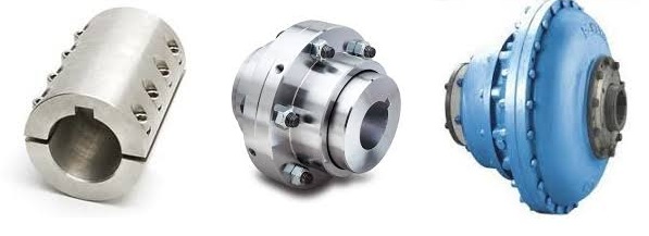
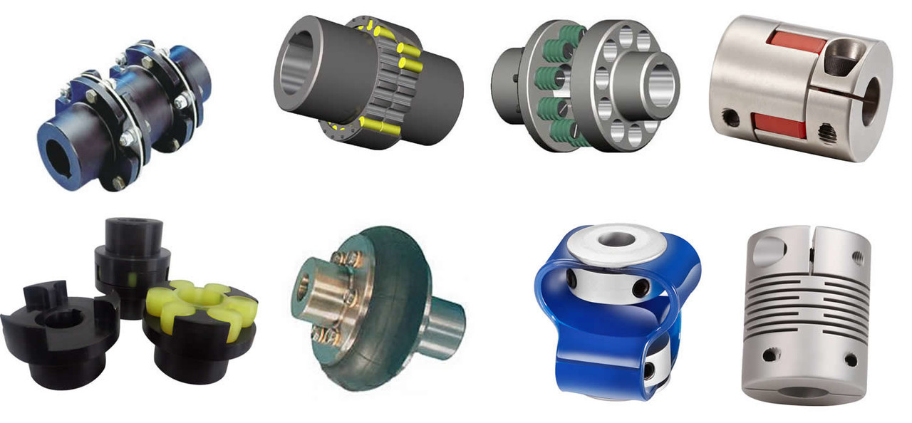
Product Description
GIC-20×20 Shaft Flange Coupling Step Motor Flexible Coupling
Description of GIC-20×20 Shaft Flange Coupling Step Motor Flexible Coupling
>Integrated structure, the overall use of high-strength aluminum alloy materials
>Elastic action compensates radial, angular and axial deviation
>No gap shaft and sleeve connection, suitable for CHINAMFG and reverse rotation
>Designed for encoder and stepper motor
>Fastening method of clamping screw
Catalogue of GIC-20×20 Shaft Flange Coupling Step Motor Flexible Coupling
|
model parameter |
common bore diameter d1,d2 |
ΦD |
L |
L1 |
L2 |
F |
M |
tightening screw torque |
|
GIC-12xl8.5 |
2,3,4,5,6 |
12 |
18.5 |
0.55 |
1.3 |
2.5 |
M2.5 |
1 |
|
GIC-16xl6 |
3,4,5,6,6.35 |
16 |
16 |
0.55 |
1.4 |
3.18 |
M2.5 |
1 |
|
GIC-16×23 |
3,4,5,6,6.35 |
16 |
23 |
0.55 |
1.4 |
3.18 |
M2.5 |
1 |
|
GIC-19×23 |
3,4,5,6,6.35,7,8 |
19 |
23 |
0.55 |
1.4 |
3.18 |
M2.5 |
1 |
|
GIC-20×20 |
4,5,6,6.35,7,8,10 |
20 |
20 |
0.55 |
1.5 |
3.75 |
M2.5 |
1 |
|
GIC-20×26 |
4,5,6,6.35,7,8,10 |
20 |
26 |
0.55 |
1.5 |
3.75 |
M3 |
1.5 |
|
GIC-25×25 |
5,6,6.35,7,8,9,9.525,10,11,12 |
25 |
25 |
0.6 |
1.7 |
4.84 |
M3 |
1.5 |
|
GIC-25×31 |
5,6,6.35,7,8,9,9.525,10,11,12 |
25 |
31 |
0.6 |
1.8 |
4.46 |
M3 |
1.5 |
|
GIC-28.5×38 |
6,6.35,8,9,9.525,10,11,12,12.7,14 |
28.5 |
38 |
0.8 |
2.1 |
5.62 |
M4 |
2.5 |
|
GIC-32×32 |
8,9,9.525,10,11,12,12.7,14,15,16 |
32 |
32 |
0.8 |
2.3 |
6.07 |
M4 |
2.5 |
|
GIC-32×41 |
8,9,9.525,10,11,12,12.7,14,15,16 |
32 |
41 |
0.8 |
2.3 |
6.02 |
M4 |
2.5 |
|
GIC-38×41 |
8,9,9.525,10,11,12,14,15,16,17,18,19 |
38 |
41 |
0.8 |
2.7 |
5.32 |
M5 |
7 |
|
GIC-40×50 |
8,9,9.525,10,11,12,14,15,16,17,18,19,20 |
40 |
50 |
0.8 |
2.7 |
6.2 |
M5 |
7 |
|
GIC-40×56 |
8,10,11,12,12.7,14,15,16,17,18,19,20 |
40 |
56 |
0.8 |
2.7 |
8.5 |
M5 |
7 |
|
GIC-42×50 |
10,11,12,12.7,14,15,16,17,18,19,20,22,24 |
42 |
50 |
0.8 |
2.7 |
6.2 |
M5 |
7 |
|
GIC-50×50 |
10,12,12.7,14,15,16,17,18,19,20,22,24,25,28 |
50 |
50 |
0.8 |
2.9 |
7.22 |
M6 |
12 |
|
GIC-50×71 |
10,12,12.7,14,15,16,17,18,19,20,222425,28 |
50 |
71 |
0.8 |
3.3 |
8.5 |
M6 |
12 |
|
model parameter |
Rated torque(N.m) |
allowable eccentricity (mm) |
allowable deflection angle (°) |
allowable axial deviation (mm) |
maximum speed (rpm) |
static torsional stiffness (N.M/rad) |
weight (g) |
|
GIC-12xl8.5 |
0.5 |
0.1 |
2 |
±0.2 |
11000 |
60 |
4.8 |
|
GIC-16xl6 |
0.5 |
0.1 |
2 |
±0.2 |
10000 |
80 |
8 |
|
GIC-16×23 |
0.5 |
0.1 |
2 |
±0.2 |
9500 |
80 |
9.3 |
|
GIC-19×23 |
1 |
0.1 |
2 |
±0.2 |
9500 |
80 |
13 |
|
GIC-20×20 |
1 |
0.1 |
2 |
±0.2 |
10000 |
170 |
14 |
|
GIC-20×26 |
1 |
0.1 |
2 |
±0.2 |
7600 |
170 |
16.5 |
|
GIC-25×25 |
2 |
0.15 |
2 |
±0.2 |
6100 |
780 |
26 |
|
GIC-25×31 |
2 |
0.15 |
2 |
±0.2 |
6100 |
380 |
29 |
|
GIC-28.5×38 |
3 |
0.15 |
2 |
±0.2 |
5500 |
400 |
51 |
|
GIC-32×32 |
4 |
0.15 |
2 |
±0.2 |
5000 |
1100 |
56 |
|
GIC-32×41 |
4 |
0.15 |
2 |
±0.2 |
500 |
500 |
65 |
|
GIC-38×41 |
6.5 |
0.2 |
2 |
±0.2 |
650 |
650 |
107 |
|
GIC-40×50 |
6.5 |
0.2 |
2 |
±0.2 |
600 |
650 |
135 |
|
GIC-40×56 |
8 |
0.2 |
2 |
±0.2 |
800 |
800 |
142 |
|
GIC-42×50 |
8.5 |
0.2 |
2 |
±0.2 |
800 |
850 |
135 |
|
GIC-50×50 |
20 |
0.2 |
2 |
±0.2 |
1000 |
1000 |
220 |
|
GIC-50×71 |
20 |
0.2 |
2 |
±0.2 |
1000 |
1000 |
330 |
/* January 22, 2571 19:08:37 */!function(){function s(e,r){var a,o={};try{e&&e.split(“,”).forEach(function(e,t){e&&(a=e.match(/(.*?):(.*)$/))&&1

Can Shaft Couplings Compensate for Angular, Parallel, and Axial Misalignments?
Yes, shaft couplings are designed to compensate for different types of misalignments between rotating shafts in mechanical power transmission systems. They can handle the following types of misalignments:
- Angular Misalignment: This occurs when the shafts are not parallel and have an angle between them. Flexible couplings, such as elastomeric, beam, or Oldham couplings, can accommodate angular misalignments by allowing slight angular movement between the shafts while transmitting torque.
- Parallel Misalignment: This happens when the shafts are not collinear, resulting in axial displacement. Flexible couplings with lateral flexibility, like elastomeric or bellows couplings, can handle parallel misalignment by allowing limited lateral movement between the shafts.
- Radial Misalignment: Radial misalignment occurs when the shafts have lateral displacement but remain parallel. Flexible couplings, such as jaw or grid couplings, can absorb radial misalignment by permitting some lateral deflection while transmitting torque.
It is essential to note that while shaft couplings can compensate for misalignments to some extent, they do have their limits. The magnitude of misalignment they can handle depends on the type and design of the coupling. Exceeding the specified misalignment capabilities of a coupling can lead to premature wear, reduced efficiency, and possible coupling failure.
Therefore, when selecting a shaft coupling for an application, it is crucial to consider the expected misalignment and choose a coupling that can accommodate the anticipated misalignment range. Additionally, maintaining proper alignment through regular maintenance and periodic inspections is essential to ensure the coupling’s optimal performance and extend its service life.
“`
Temperature and Speed Limits for Different Shaft Coupling Types
The temperature and speed limits of shaft couplings vary depending on the materials and design of the coupling. Manufacturers provide specific guidelines and ratings for each coupling type. Below are general temperature and speed limits for some common shaft coupling types:
1. Elastomeric Couplings:
Elastomeric couplings, such as jaw couplings and tire couplings, typically have temperature limits ranging from -40°C to 100°C (-40°F to 212°F). The speed limits for elastomeric couplings are generally up to 5,000 RPM, but some designs may allow higher speeds.
2. Metallic Couplings:
Metallic couplings, like gear couplings and disc couplings, can handle a wider temperature range, typically from -50°C to 200°C (-58°F to 392°F). The speed limits for metallic couplings vary based on the size and design, but they can range from 3,000 RPM to over 10,000 RPM.
3. Grid Couplings:
Grid couplings have temperature limits similar to metallic couplings, ranging from -50°C to 200°C (-58°F to 392°F). The speed limits for grid couplings are typically in the range of 3,000 to 5,000 RPM.
4. Oldham Couplings:
Oldham couplings usually have temperature limits from -30°C to 100°C (-22°F to 212°F) and speed limits ranging from 1,000 to 5,000 RPM.
5. Beam Couplings:
Beam couplings generally have temperature limits from -40°C to 120°C (-40°F to 248°F) and speed limits between 5,000 to 10,000 RPM.
6. Fluid Couplings:
Fluid couplings are suitable for a wide range of temperatures, often from -50°C to 300°C (-58°F to 572°F). The speed limits depend on the size and design of the fluid coupling but can extend to several thousand RPM.
It’s important to note that these are general guidelines, and the actual temperature and speed limits may vary based on the specific coupling manufacturer, material quality, and application requirements. Always refer to the manufacturer’s documentation and technical specifications for accurate and up-to-date temperature and speed limits for a particular shaft coupling model.
“`
Best Practices for Installing a Shaft Coupling for Optimal Performance
Proper installation of a shaft coupling is crucial for ensuring optimal performance and preventing premature wear or failure. Follow these best practices to install a shaft coupling correctly:
1. Shaft Alignment:
Ensure that both the driving and driven shafts are properly aligned before installing the coupling. Misalignment can lead to increased stress on the coupling and other connected components, reducing efficiency and causing premature wear. Use alignment tools, such as dial indicators or laser alignment systems, to achieve accurate shaft alignment.
2. Cleanliness:
Before installation, clean the shaft ends and the coupling bore thoroughly. Remove any dirt, debris, or residue that could interfere with the coupling’s fit or cause misalignment.
3. Lubrication:
Apply the recommended lubricant to the coupling’s contact surfaces, such as the bore and shaft ends. Proper lubrication ensures smooth installation and reduces friction during operation.
4. Correct Fit:
Ensure that the coupling is the correct size and type for the application. Use couplings with the appropriate torque and speed ratings to match the equipment’s requirements.
5. Fastening:
Use the recommended fastening methods, such as set screws or keyways, to securely attach the coupling to the shafts. Make sure the fasteners are tightened to the manufacturer’s specifications to prevent loosening during operation.
6. Spacer or Adapter:
If required, use a spacer or adapter to properly position the coupling on the shafts and maintain the desired distance between the driving and driven components.
7. Avoid Shaft Damage:
Be careful during installation to avoid damaging the shaft ends, especially when using set screws or other fastening methods. Shaft damage can lead to stress concentrations and eventual failure.
8. Check Runout:
After installation, check the coupling’s runout using a dial indicator to ensure that it rotates smoothly and without wobbling. Excessive runout can indicate misalignment or improper fit.
9. Periodic Inspection:
Regularly inspect the coupling and its components for signs of wear, misalignment, or damage. Perform routine maintenance as recommended by the manufacturer to prevent issues from worsening over time.
10. Follow Manufacturer’s Guidelines:
Always follow the manufacturer’s installation instructions and guidelines. Different types of couplings may have specific installation requirements that need to be adhered to for optimal performance and safety.
By following these best practices, you can ensure that your shaft coupling is installed correctly, maximizing its efficiency and reliability in your mechanical power transmission system.
“`

editor by CX 2024-04-15